Rated Load and Nominal Life
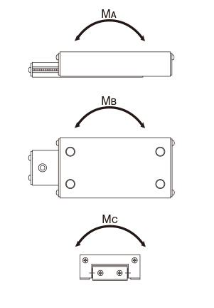
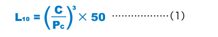
Rated Loads in All Directions
The rated loads of models LS, LSP and LSC are identical in the vertical and horizontal directions.
Static Safety Factor fS
Linear Ball Slide models LS, LSP or LSC may receive an unexpected external force while it is stationary or operative due to the generation of an inertia caused by vibrations and impact or start and stop. It is necessary to consider a static safety factor against such a working load.

| fS | Static Safety Factor |
|---|---|
| C0 | Basic static load rating (N) |
| M0 | Static permissible moment (MA・MB・MC) (N・m) |
| PC | Calculated load (N) |
| M | Calculated moment (N・m) |
Reference Value of Static Safety Factor
The static safety factors indicated in Table1 are the lower limits of reference values in the respective conditions.
| Machine using the LM system |
Load conditions | Lower limit of fs |
|---|---|---|
| General industrial machinery |
Without vibration or impact | 1 to 1.3 |
| With vibration or impact | 2 to 7 |
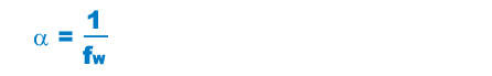
Calculating the Nominal Life
The nominal life of the THK linear ball slide is defined as 50 km. The nominal life (L10) is calculated from the basic dynamic load rating (C) and the load acting on the linear ball slide (PC) using the following formula.
| L10 | Nominal life (km) |
|---|---|
| C | Basic dynamic load rating (kN) |
| PC | Calculated load (kN) |
When comparing the nominal life (L10), you must take into account whether the basic dynamic load rating was defined based on 50 km or 100 km. Convert the basic dynamic load rating based on ISO 14728-1 as necessary.
ISO-regulated basic dynamic load rating conversion formulas:

| C50 | Basic dynamic load rating based on a nominal life of 50 km |
|---|---|
| C100 | Basic dynamic load rating based on a nominal life of 100 km |
Calculating the Modified Nominal Life
During use, a linear ball slide may be subjected to vibrations and shocks as well as fl uctuating loads, which are difficult to detect. Taking these factors into account, the modified nominal life (L10m) can be calculated according to the following formula (2).
Modified factor α
| α | Modified factor |
|---|---|
| fW | Load factor (see Table 2) |
Modified nominal life L10m

| L10m | Modified nominal life (km) |
|---|---|
| C | Basic dynamic load rating (kN) |
| PC | Calculated load (kN) |
Calculating the Service Life Time
When the nominal life (L10) has been obtained, if the stroke length and the number of reciprocations per minute are constant, the service life time is obtained using the following formula.

| Lh | Service life time (h) |
|---|---|
| ℓS | Stroke length (mm) |
| n1 | Number of reciprocations per minute(min-1) |
fW : Load Factor
In general, reciprocating machines tend to experience vibrations or impacts during operation, and it is difficult to accurately determine the vibrations generated during high-speed operation and impacts during frequent starts and stops. Therefore, when the actual load applied to a Model VR or VB cannot be obtained, or when speed and vibrations have a significant influence, divide the basic dynamic load rating (C) by the corresponding load factor in Table 2 , which has been empirically obtained.
| Vibrations/ impact |
Speed (V) | fW |
|---|---|---|
| Faint | Very low V≦0.25m/s |
1 to 1.2 |
| Weak | Slow 0.25<V≦1m/s |
1.2 to 1.5 |