Rated Load and Nominal Life
Load Rating
The basic load ratings for model ST are indicated in the respective specification tables.
Calculating the Nominal Life
The nominal life of model ST is obtained using the following equation.
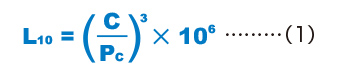
| L10 | Nominal life (rev.) (The total number of revolutions that 90% of a group of identical LM strokes independently operating under the same conditions can achieve without showing flaking) |
|---|---|
| C | Basic dynamic load rating (N) |
| Pc | Calculated radial load (N) |
Calculating the Modifi ed Nominal Life
During use, an LM stroke may be subjected to vibrations and shocks as well as fluctuating loads, which are difficult to detect. In addition, the hardness of the raceways, the operating temperature, and having LM strokes arranged in close contact will have a decisive impact on the service life. Taking these factors into account, the modified nominal life (L10m) can be calculated according to the following formula (2).
Modified factor α
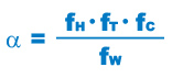
| α | Modified factor |
|---|---|
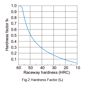
| fH | Hardness factor (see Fig.2) |
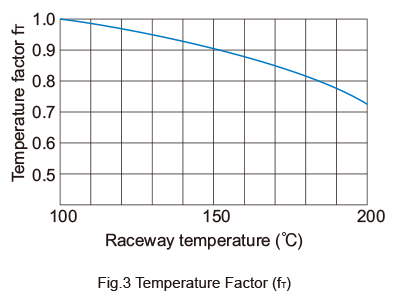
| fT | Temperature factor (see Fig.3) |
| fC | Contact factor (see Table1) |
| fW | Load factor (see Table 2) |
Modified nominal life L10m
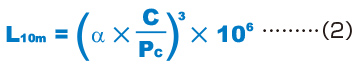
| L10m | Modified nominal life (rev.) |
|---|---|
| C | Basic dynamic load rating (N) |
| PC | Calculated radial load (N) |
When a Moment Load is Applied to a Single Nut
When a moment load is applied to a single nut, calculate the equivalent radial load from the moment.

| Pu | Equivalent radial load (N)(with moment load) |
|---|---|
| K | Equivalent factor (see Table3 to Table4) |
| M | Applied moment (N・mm) |
Pu is assumed to be within the Basic Static Load Rating (C0).
When a Moment Load and a Radial Load are Simultaneously Applied
When a moment and a radial load are applied simultaneously, calculated the service life based on the sum of the radial load and the equivalent radial load.
Calculating the Service Life Time
When the nominal life (L10) has been obtained, if the number of revolutions per minute and the number of reciprocations per minute are constant, the service life time is obtained using the following formulas.
For Rotating Motion or Complex Motion
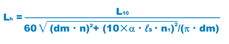
For Reciprocating Motion
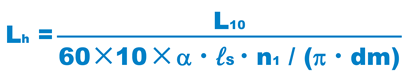
| Lh | Service life time (h) |
|---|---|
| n | Revolutions per minute (min-1) |
| n1 | Number of reciprocations per minute(min-1) |
| ℓs | Stroke length (mm) |
| dm | Pitch circle diameter (mm)(dm≒1.15×dr) |
| dr | Ball inscribed bore diameter (mm) |
| α | Factor for cage material(α=0.7) |
Tolerance Value in Rotation and Reciprocating Speed
The permissible speed limit of model ST is obtained using the following equation.

For the DN value above, the following value applies as a standard value.
| For oil lubrication | DN=600000 |
|---|---|
| For grease lubrication | DN=300000 |
However, the following points must be taken into account. n ≦5000 ℓS・n1≦50000
fH : Hardness Factor
To maximize the load capacity of model ST, the hardness of the raceways needs to be between 58 to 64 HRC. If the hardness is lower than this range, the basic dynamic load rating and the basic static load rating decrease. Therefore, it is necessary to multiply each rating by the respective hardness factor (fH). Normally, fH=1.0 since model ST has sufficient hardness.
fT : Temperature Factor
If the temperature of the environment surrounding the operating model ST exceeds 100℃, take into account the adverse effect of the high temperature and multiply the basic load ratings by the temperature factor indicated in Fig.3 .
Note) If the environment temperature exceeds 80℃, contact THK.
fc : Contact Factor
When multiple nuts of model ST are used in close contact with each other, their linear motion is affected by moments and mounting accuracy, making it difficult to achieve uniform load distriution. In such applications, multiply the basic load rating (C) and (C0) by the corresponding contact factor in Table1 .
Note) If uneven load distribution is expected in a large machine, take into account the respective contact factor indicated in table 1.
| Number of nuts in close contact with each other |
Contact factor fc |
|---|---|
| 2 | 0.81 |
| 3 | 0.72 |
| 4 | 0.66 |
| 5 | 0.61 |
| Normal use | 1 |
fw : Load Factor
In general, reciprocating machines tend to experience vibrations or impacts during operation, and it is extremely difficult to accurately determine the vibrations generated during highspeed operation and impacts during frequent starts and stops. Therefore, when speed and vibrations have a significant influence, divide the basic dynamic load rating (C) by the corresponding load factor in Table 2 , which has been empirically obtained.
| Vibrations/ impact |
Speed (V) | fw |
|---|---|---|
| Faint | Very low V≦0.25m/s |
1 to 1.2 |
| Weak | Slow 0.25<V≦1m/s |
1.2 to 1.5 |
| Medium | Medium 1<V≦2m/s |
1.5 to 2 |
| Strong | High V>2m/s |
1.5 to 2 |