May 13, 2026
Products
Circular Arc Grooves and the DF Configuration: LM Guide Features that Support Smooth Motion in Machines
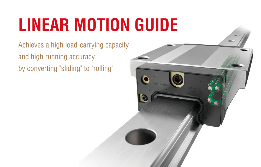
Wherever high accuracy and reliability are required, industrial machinery like machine tools, semiconductor manufacturing equipment, and industrial robots contain a critical component that provides smooth, precise linear motion. Known as the LM (Linear Motion) Guide, this component facilitates straight, smooth, and precise motion and contributes greatly to equipment performance and life.
It was first developed by THK as a groundbreaking way of incorporating rolling motion in a linear motion part. THK now boasts a full lineup of LM Guide products with a variety of different features, but two things most of our mainstays have in common are circular arc grooves and balls arranged in a DF configuration. This time, we’ll highlight the rationale behind LM Guide groove shape and groove contact structure, explaining the benefits provided by the interplay of these two factors without getting overly technical.
LM Guide Raceway Grooves: The Impact of Groove Shape on Performance
LM Guide Raceway Grooves
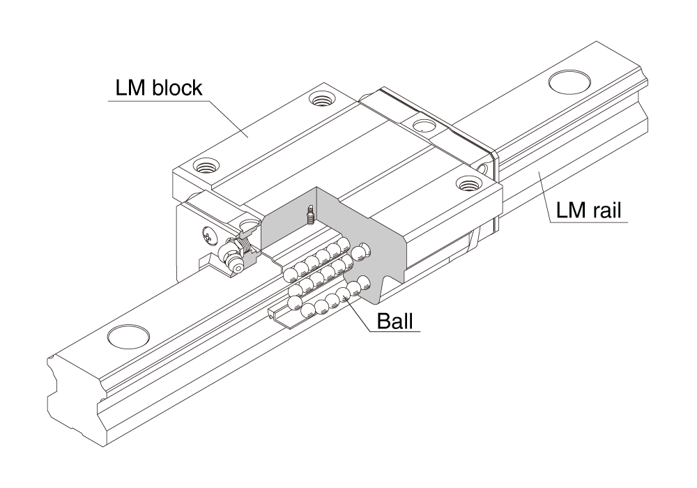
An LM Guide is composed of three basic elements: a mobile LM block, an LM rail that supports its motion, and balls that roll along what are called raceway grooves. The shape of these raceway grooves is a crucial design factor that impacts the kinematic performance and service life of an LM Guide.
Two-Point Contact vs. Four-Point Contact: Characteristics of Different Groove Shapes
An LM Guide incorporates a large number of balls packed into the space between an LM block and the LM rail, and the way these balls make contact with the raceway grooves plays a large role in determining the characteristics of the LM Guide overall.
Generally speaking, the grooves of an LM Guide will be one of two shapes.
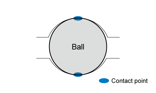
Circular arc grooves
The shape of a circular arc groove is defined by a single curve. Balls make contact with these grooves at two different points.
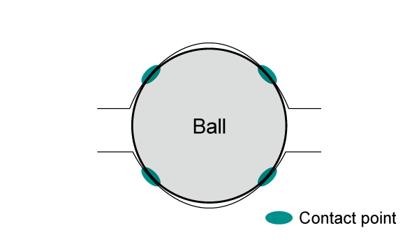
Gothic-arch grooves
The shape of a Gothic-arch groove is formed by combining two different curves. Balls make contact with these grooves at four different points.
Different Uses for Circular Arc Grooves and Gothic-Arch Grooves
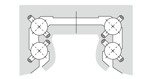
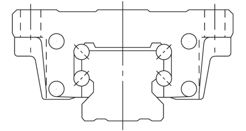
In order for an LM Guide to bear both vertical and horizontal loads, its balls must make contact with its grooves at a total of eight different points. The examples below show the structures generally used to meet this requirement.
Four circular arc grooves (with two points of contact each)
Two Gothic-arch grooves (with four points of contact each)
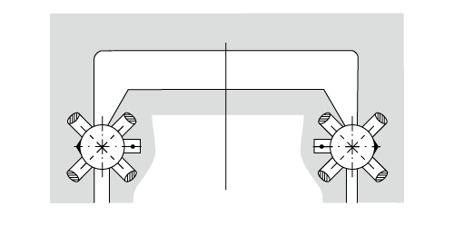
Gothic-arch grooves are often used for things like miniature LM Guide models in cases where load capacity requirements would otherwise be more constrained by a limited cross-sectional area.
The Importance of Raceway Groove Shape
The Mechanism behind Differential Slip
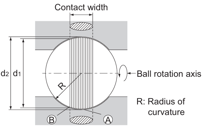
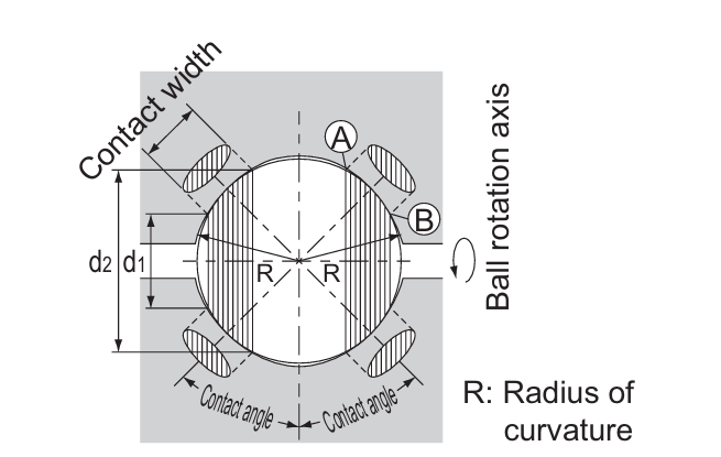
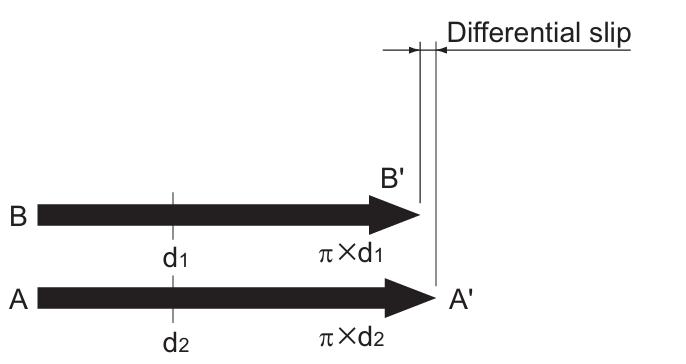
The kinematic performance of an LM Guide is greatly affected by the way the balls rotate as they move. As they rotate, the balls roll, but the surface speed at which they do so changes based on where they are. This is because their distance from the axis of rotation changes as they move. The farther a ball is from the axis of rotation, the longer its travel distance (circumference of travel) becomes, and the faster it moves. Conversely, the closer a ball is to the axis of rotation, the shorter its travel distance becomes, and the slower it moves.
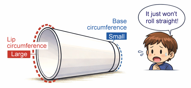
Because balls move at a set speed, forcing them to do so inside a contact structure with a defined contact width causes some of them to slip. You can think of it like trying to roll a paper cup on its side. The lip of the cup and the base of the cup have different circumferences, so you would need to slide part of the cup sometimes to keep it rolling forward in a straight line. The idea here is basically the same.
With the four-point contact structure of Gothic-arch grooves, any installation error or misalignment has considerable consequences. If the balls don’t make contact with the grooves at all four points simultaneously, it becomes impossible to keep them moving the way they should. What ultimately happens is that they end up sliding instead of rolling, in a phenomenon called differential slip.
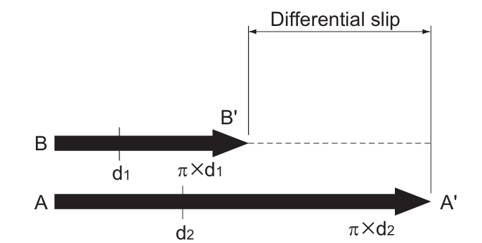
Too much differential slip creates friction that generates heat and accelerates wear, diminishing the kinematic performance of an LM Guide and reducing its service life.
With the two-point contact structure provided by circular arc grooves, though, there’s less of a difference between the circumferences of travel for each ball, which makes it possible to keep them all rolling naturally. This reduces differential slip and provides three crucial characteristics sought from an LM Guide:
- Smooth motion
- Reduced heat generation
- Reduced wear
The Self-Adjustment Capability of the DF Configuration: Two-Point Contact That Absorbs Mounting Error
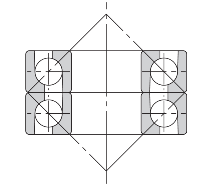
No matter how accurate an LM Guide may be, installing it on an actual piece of equipment may introduce some degree of error or tilt. This is where the DF (face-to-face) configuration of the balls comes into play. In a DF configuration, four rows of balls are split into two pairs such that the rows in each pair face each other and their lines of action from applied load converge toward the center of the system.
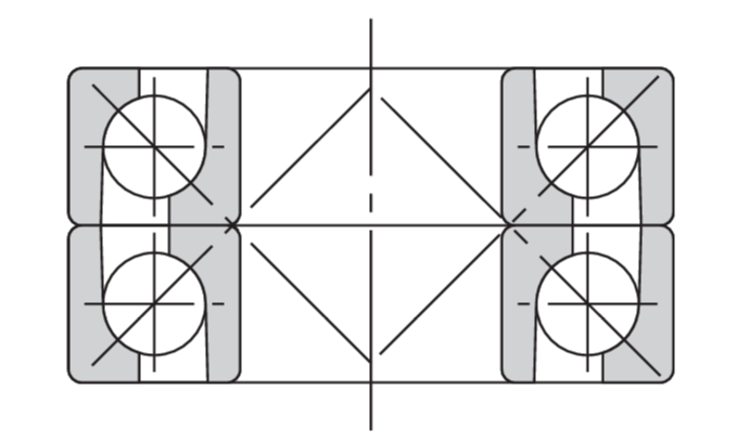
This internal structure is largely unaffected by mounting error
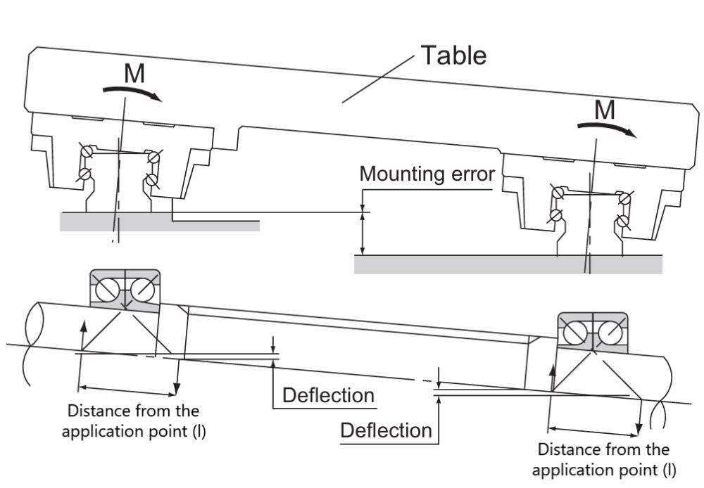
The short distance between application points (l) allows for a large permissible tilt angle, providing a high degree of self-adjustment
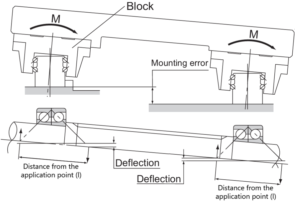
In a DB (back-to-back) configuration, however, the lines of action from loads applied to rows of balls facing each other converge away from the center of the system.
The self-adjustment capability (the ability of an LM Guide to absorb mounting error inwardly) is the most valuable outcome of combining circular arc grooves with a DF ball configuration. The orientation of the balls inside an LM block makes it possible to absorb error or tilting* on the surface to which the LM rail is mounted without generating an internal load. This limits any increase in rolling resistance, makes it easier to maintain stable motion, and helps prevent diminished service life.
* See the mounting surface error reference values listed in the THK catalog prior to use.
Combining Circular Arc Grooves with a DF Ball Configuration
Using circular arc grooves together with a DF ball configuration provides three benefits that are critical for equipment design:
- Smooth kinetic performance
- Long service life
- Mounting error absorption
Using a Deeper Understanding of Groove Shapes to Select the Optimal LM Guide
While this article took a closer look at the features of circular arc grooves used in some types of LM Guide, there are also many instances where the application or design conditions favor the compactness of miniature LM Guide models made possible by Gothic-arch grooves instead. Both groove shapes have a proven record of being useful in different situations.
While groove shape may seem like a minor factor, as a design consideration, it has a major impact on equipment performance. Understanding the pros and cons of each groove shape is key to picking the right LM Guide for a given application.
If you’re trying to figure out which LM Guide is right for you, don't hesitate to contact THK for support.
LM Guide (THK website)* This content is based on information that was released in Japanese on May 13, 2026.