Assembling the Ball Spline
Mounting the Spline
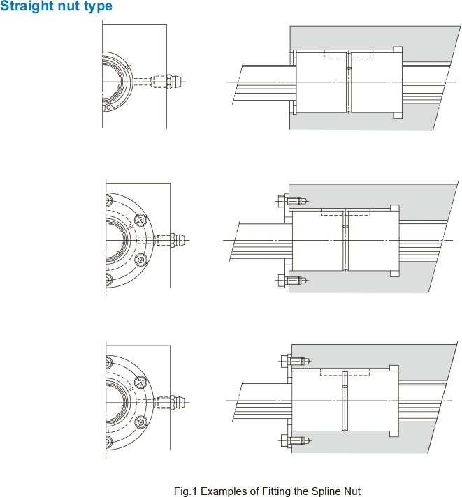
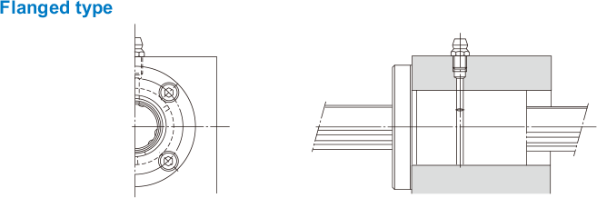
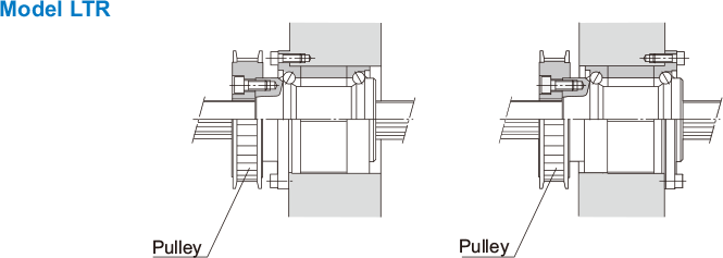
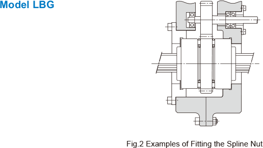
Fig.1 and Fig.2 shows examples of mounting the spline nut. Although the Ball Spline does not require a large strength for securing it in the spline shaft direction, do not support the spline only with driving fitting.
Note) On both ends of the spline nut of Caged Ball Ball Spline model SLS, resin end caps are installed. Hitting them or pressing hard may cause damage. You must take care not to apply an excessive load.
Installing the Spline Nut
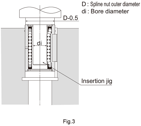
When installing the spline nut into the housing, do not hit the side plate or the seal, but gentlyinsert it using a jig ( Fig.3 ).
| Nominal shaft diameter | 15 | 20 | 25 | 30 | 40 | 50 | 60 | 70 | 85 | 100 | 120 | 150 |
|---|---|---|---|---|---|---|---|---|---|---|---|---|
| di | 12.5 | 16.1 | 20.3 | 24.4 | 32.4 | 40.1 | 47.8 | 55.9 | 69.3 | 83.8 | 103.8 | 131.8 |
| Nominal shaft diameter | 6 | 8 | 10 | 13 | 16 | 20 | 25 | 30 | 40 | 50 | 60 | 80 | 100 |
|---|---|---|---|---|---|---|---|---|---|---|---|---|---|
| di | 5.0 | 7 | 8.5 | 11.5 | 14.5 | 18.5 | 23 | 28 | 37.5 | 46.5 | 56 | 75.5 | 94.5 |
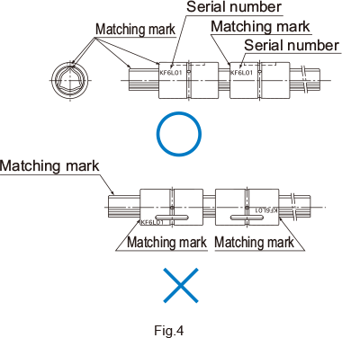
Installation of the Spline Shaft
When installing the spline shaft into the spline nut, identify the matching marks ( Fig.4 ) on the spline shaft and the spline nut, and then insert the shaft straightforward while checking their relative positions.Note that forcibly inserting the shaft may cause balls to fall off .If the spline nut is attached with a seal or given a preload, apply a lubricant to the outer surface of the spline shaft.