Rated Load and Nominal Life
Rated Loads in All Directions
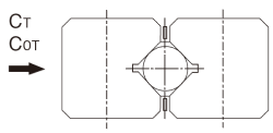
The basic load ratings (CZ and C0Z) in the specification table indicate the values per rolling element in the directions shown in the figure. When obtaining the nominal life, calculate the basic load ratings (C0) of the actually used rolling elements from the equation below.
| CZ | Basic dynamic load rating per rolling element in the specification table (kN) |
|---|---|
| C0Z | Basic static load rating per rolling element in the specification table (kN) |
| Z | Number of rolling elements used (number of rolling elements within the effective load range) |
| P | Roller pitch (Refer to pages Cross-Roller Guide Model VR ) |
For Model VR
| Load direction |
 |
 |
|---|---|---|
| Basic dynamic load rating C (kN) |
 |
 |
| Basic static load rating C0(kN) |
 |
 |
* For Z/2 , truncate the decimals.
For Model VB
| Load direction |
 |
 |
|---|---|---|
| Basic dynamic load rating C (kN) |
 |
 |
| Basic static load rating C0(kN) |
 |
 |
Static Safety Factor fS
Models VR and VB may receive an unexpected external force while it is stationary or operative due to the generation of an inertia caused by vibrations and impact or start and stop. It is necessary to consider a static safety factor against such a working load.

| fS | Static safety factor (see Table1) |
|---|---|
| C0 | Basic static load rating (kN) |
| Pc | Calculated load (kN) |
| Load conditions1 | Lower limit of fs |
|---|---|
| Without vibration or impact | 1 to 1.3 |
| With vibration or impact | 2 to 3 |
- 1 In general, factors that cause vibration and impacts include acceleration and deceleration, sudden starts and stops, transmission of vibration and impacts from external devices and machines, and changes in processing force over time.
Calculating the Nominal Life
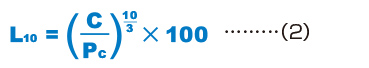
The nominal life is defined as 50 km for a THK LM Guide with balls and 100 km for an LM Guide with rollers. The nominal life (L10) is calculated from the basic dynamic load rating (C) and the load acting on the LM Guide (PC) using the following formulas.
-
LM Guide with balls (50 km basic dynamic load rating)
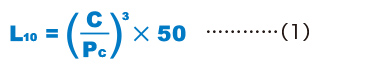
L10 Nominal life (km) C Basic dynamic load rating (kN) PC Calculated load (kN) -
LM Guide with rollers (100 km basic dynamic load rating)
When comparing the nominal life (L10), you must take into account whether the basic dynamic load rating was defined based on 50 km or 100 km. Convert the basic dynamic load rating based on ISO 14728-1 as necessary.
ISO-regulated basic dynamic load rating conversion formulas:
-
LM Guide with balls

C50 Basic dynamic load rating based on a nominal life of 50 km C100 Basic dynamic load rating based on a nominal life of 100 km -
LM Guide with rollers

Calculating the Modified Nominal Life
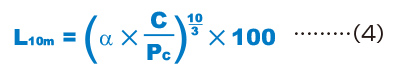
During use, a cross-roller guide/ball guide may be subjected to vibrations and shocks as well as fluctuating loads, which are difficult to detect. In addition, the surface hardness of the raceways, the operating temperature, and having blocks arranged directly behind one another will have a decisive impact on the service life. Taking these factors into account, the modified nominal life (L10m) can be calculated according to the following formulas (3) and (4).
Modified factor α
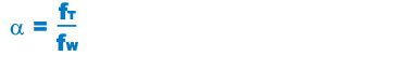
| α | Modified factor |
|---|---|
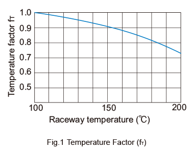
| fT | Temperature factor (see Fig.1 on A7-6) |
| fW | Load factor (see Table 2 on A7-6) |
Modified nominal life L10m
-
LM Guide with balls
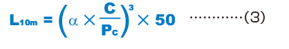
L10m Modified nominal life (km) C Basic dynamic load rating (kN) PC Calculated load (kN) -
LM Guide with rollers
Calculating the Service Life Time
When the nominal life (L10) has been obtained, if the stroke length and the number of reciprocations per minute are constant, the service life time is obtained using the following equation.

| Lh | Service life time (h) |
|---|---|
| ℓS | Stroke length (mm) |
| n1 | Number of reciprocations per minute(min-1) |
fT : Temperature Factor
If the temperature of the environment surrounding the operating model VR or VB exceeds 100℃, take into account the adverse effect of the high temperature and multiply the basic load ratings by the temperature factor indicated in Fig.1 .
Note) If the environment temperature exceeds 100℃, con- tact THK.
fw : Load Factor
In general, reciprocating machines tend to experience vibrations or impacts during operation, and it is difficult to accurately determine the vibrations generated during high-speed operation and impacts during frequent starts andstops. Therefore, when the actual load applied to a Model VR or VB cannot be obtained, or when speed and vibrations have a significant influence, divide the basic dynamic load rating (C) by the corresponding load factor in Table 2 , which has been empirically obtained.
| Vibrations/ impact |
Speed (V) | fw |
|---|---|---|
| Faint | Very low V≦0.25m/s |
1 to 1.2 |
| Weak | Slow 0.25<V≦1m/s |
1.2 to 1.5 |