Linear Bushing LM Shafts / LM Shaft End Support Model SF
LM shafts for use with the high quality linear. Machined shaft ends available upon request. bushing model LM series.
Shaft diameter : 3,4,5,6,8,10,12,13,16,20,25,30,35,38,40,50,60,80,100
Select display items
Click on the feature tag you wish to view and press the button to display. Detailed information is displayed at the bottom of the screen.
- Select all
- Deselect all
Detailed information
-
 Easy product comparisonsHighlight feature
 -
 Save items for laterreview Favorites feature
THK Online Services
Member-Exclusive Content
These contents can be accessed
after registering as a member.
Benefit 1: Useful features
Benefit 2: Exclusive content
| Products | Contents |
|---|---|
| LM Guide | LM rail standard lengths and maximum length, tapped-hole type LM rail, frame for LM rail clamps, steel plate for LM rail clamps, etc. |
| Ball Screw | Axial clearance, maximum manufacturing length of shaft, etc. |
| Actuator | Movable part mass, etc. |
Optional
Lubrication
- Lubrication
Rustprevention
- Material and Surface Treatment
- Dust prevention
Display result
- Detailed information
- Dimensional drawing/Dimensional table
- Optional
Detailed information
Dimensional drawing/Dimensional table
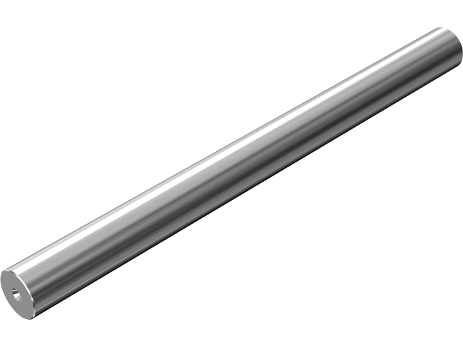
THK manufactures high quality, dedicated LM shafts for linear bushings.
- (1) [Major materials]
SUJ2 (high-carbon chromium bearing steel)
THK5SP (THK standard material)
SUS440C equivalent
[Hardness] 58 to 64 HRC (SUJ2, THK5SP), 56 HRC or above (SUS440C or equivalent)
[Hardened layer depth] 0.8 to 2.5 mm (varies with shaft diameter)
[Surface roughness] Ra 0.4 or less
[Straightness of the LM shaft] 50μm/300 mm or less - (2) Precision-grade LM shafts with shaft diameter tolerance of g5 or h5 are also manufactured as standard.
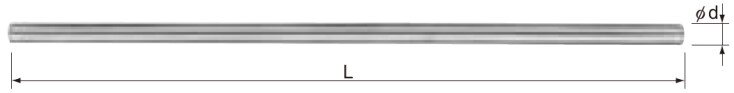
Unit: mm
| Model No. |
|---|
| Shaft diameter |
Manufactured length L | ||
|---|---|---|---|
| d | Tolerance | Min length | Max length |
| g6 mm | |||
| 3 | ?2 ?8 |
20 | 400 |
| 4 | ?4 ?12 |
20 | 400 |
| 5 | ?4 ?12 |
20 | 500 |
| 6 | ?4 ?12 |
20 | 1500 |
| 8 | ?5 ?14 |
20 | 1500 |
| 10 | ?5 ?14 |
30 | 1500 |
| 12 | ?6 ?17 |
30 | 1500 |
| 13 | ?6 ?17 |
30 | 1500 |
| 16 | ?6 ?17 |
40 | 3000 |
| 20 | ?7 ?20 |
40 | 3000 |
| 25 | ?7 ?20 |
50 | 3000 |
| 30 | ?7 ?20 |
60 | 3000 |
| 35 | ?9 ?25 |
70 | 3000 |
| 38 | ?9 ?25 |
100 | 3000 |
| 40 | ?9 ?25 |
100 | 3000 |
| 50 | ?9 ?25 |
100 | 3000 |
| 60 | ?10 ?29 |
200 | 3000 |
| 80 | ?10 ?29 |
200 | 3000 |
| 100 | ?12 ?34 |
200 | 3000 |
Note) *Made to order
Notes on dimensional table
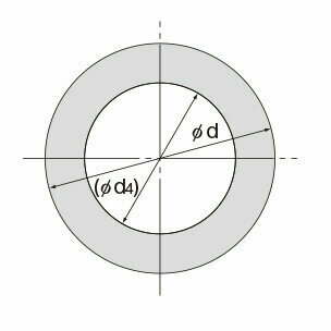
Dimensions of Hollow LM Shafts
If a hollow LM shaft is required for purposes such as weight reduction, use the desired material from Table1 for the dimensions of hollow LM shafts that THK keeps in stock.
| Supported model numbers |
LM shaft outer diameter d |
Inner diameter (ød4) |
Mass (kg/m) |
|
|---|---|---|---|---|
| Solid shaft | Hollow shaft | |||
| LM 8 | 8 | 3 | 0.4 | 0.34 |
| LM 10 | 10 | 4 | 0.62 | 0.52 |
| LM 12 | 12 | 6 | 0.89 | 0.67 |
| LM 13 | 13 | 7 | 1.05 | 0.75 |
| LM 16 | 16 | 9 | 1.59 | 1.09 |
| LM 20 | 20 | 10 | 2.47 | 1.86 |
| LM 20 | 20 | 14 | 2.47 | 1.26 |
| LM 25 | 25 | 15 | 3.86 | 2.47 |
| LM 30 | 30 | 16 | 5.56 | 3.98 |
| LM 35 | 35 | 20 | 7.57 | 5.1 |
| * LM 38 | 38 | 22 | 8.92 | 5.93 |
| LM 40 | 40 | 22 | 9.88 | 6.89 |
| LM 50 | 50 | 25 | 15.5 | 11.6 |
| LM 60 | 60 | 32 | 22.3 | 16.0 |
| * LM 80 | 80 | 52.5 | 39.6 | 22.5 |
| * LM 100 | 100 | 67.5 | 61.8 | 33.7 |
Models marked with "*" are build-to-order items.
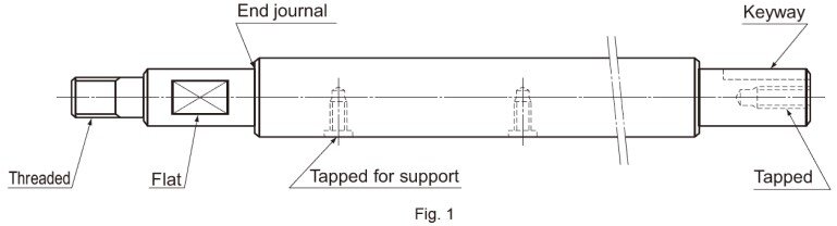
Specially Machined Types
THK also supports special machining processes such as tapping, milling, threading, through hole and end journals, as shown in the Fig.1 , at your request.
Dedicated Shafts
As the dedicated shafts for linear bushings come into direct contact with the ball bearings, the manufacturing tolerances for hardness, surface roughness, and the dimensional precision of the shaft are tight.When manufacturing dedicated shafts, the surface hardness of the shaft will have a large impact on the overall service life. Check the following material and heat treatment specifications.
Material
Generally, the following materials are used for surface hardening through induction-hardening.・ SUJ2 (JIS G 4805: high-carbon chromium bearing steel)・ SK3 to 6 (JIS G 4401: carbon tool steel)・ S55C (JIS G 4051: carbon steel for machine structural use)For special applications, martensite stainless steel SUS440C, which is corrosion resistant, may also be used.
Hardness
We recommend surface hardness of 58 HRC (≒653 HV) or higher. The depth of the hardened layer is determined by the size of the Linear Bushing; we recommend approximately 2 mm for general use.
Surface Roughness
To achieve smooth motion, the surface should preferably be finished to Ra0.40 or less.
Table of Rows of Balls and Masses for Clearance-adjustable Types and Open Types of the Linear Bushing
| Shaft diameter |
Clearance-adjustable Type | Open Type | ||||
|---|---|---|---|---|---|---|
| Model No. | Rows of balls |
Mass g |
Model No. | Rows of balls |
Mass g |
|
| 6 | LM 6-AJ | 4 | 7.8 | - | - | - |
| 8 | LM 8S-AJ | 4 | 10 | - | - | - |
| LM 8-AJ | 4 | 14.7 | - | - | - | |
| 10 | LM 10-AJ | 4 | 29 | - | - | - |
| 12 | LM 12-AJ | 4 | 31 | - | - | - |
| 13 | LM 13-AJ | 4 | 42 | LM 13-OP | 3 | 34 |
| 16 | LM 16-AJ | 5(4) | 68 | LM 16-OP | 4(3) | 52 |
| 20 | LM 20-AJ | 5 | 85 | LM 20-OP | 4 | 69 |
| 25 | LM 25-AJ | 6(5) | 216 | LM 25-OP | 5(4) | 188 |
| 30 | LM 30-AJ | 6 | 245 | LM 30-OP | 5 | 210 |
| 35 | LM 35-AJ | 6 | 384 | LM 35-OP | 5 | 350 |
| 38 | LM 38-AJ | 6 | 475 | LM 38-OP | 5 | 400 |
| 40 | LM 40-AJ | 6 | 579 | LM 40-OP | 5 | 500 |
| 50 | LM 50-AJ | 6 | 1560 | LM 50-OP | 5 | 1340 |
| 60 | LM 60-AJ | 6 | 1820 | LM 60-OP | 5 | 1650 |
| 80 | LM 80-AJ | 6 | 4320 | LM 80-OP | 5 | 3750 |
| 100 | LM 100-AJ | 6 | 8540 | LM 100-OP | 5 | 7200 |
| 120 | LM 120-AJ | 8 | 14900 | LM 120-OP | 6 | 11600 |
- Note) The numbers of ball rows in the table apply to types using a resin retainer. Those of types using a metal retainer are indicated in parentheses.
Model Number Coding
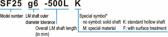
* If two or more symbols are given, they are shown in an alphabetical order.
THK Online Services
Member-Exclusive Content
These contents can be accessed
after registering as a member.
Benefit 1: Useful features
-
Easy product comparisonsHighlight feature
-
Save items for laterreview Favorites feature
Benefit 2: Exclusive content
| Products | Contents |
|---|---|
| LM Guide | LM rail standard lengths and maximum length, tapped-hole type LM rail, frame for LM rail clamps, steel plate for LM rail clamps, etc. |
| Ball Screw | Axial clearance, maximum manufacturing length of shaft, etc. |
| Actuator | Movable part mass, etc. |
Optional
No option tag has been selected.
Check detailed information with the tool
Click on the icon for the item you want to see in detail. Member registration and login are required for use.
Designer is the former optimal product selection tool
You can download 2D/3D CAD by clicking on the icon and selecting from the CAD format.
| Model No. | Designer* | Life Calculator* | CAD Download* | Catalog Download | Manual Download |
|---|---|---|---|---|---|
| SF 3 | |||||
| SF 4 | |||||
| SF 5 | |||||
| SF 6 | |||||
| SF 8 | |||||
| SF 10 | |||||
| SF 12 | |||||
| SF 13 | |||||
| SF 16 | |||||
| SF 20 | |||||
| SF 25 | |||||
| SF 30 | |||||
| SF 35 | |||||
| SF 38 | |||||
| SF 40 | |||||
| SF 50 | |||||
| SF 60 | |||||
| SF 80 | |||||
| SF 100 |
*marks are not available for guest members.