LM Stroke Miniature Stroke Model MST
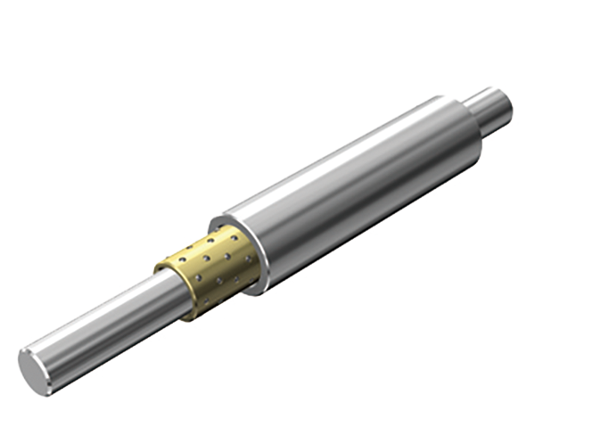
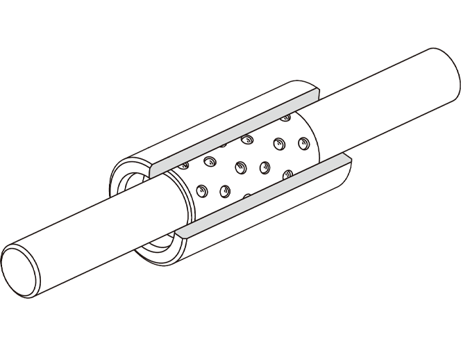
Model MST consists of an ST shaft, ball cage and nut. These components can freely be combined according to the application. The sectional shape is small, the clearance is minimal and the motion is extremely light and smooth.
Types
Highlight feature tags
- High accuracy
- Compact
- Low friction (other linear motion guides)
- High accuracy
- Compact
- Low friction (other linear motion guides)
Permissible load N : 68.6 to 216
Features
Structure and Features

Model MST consists of an ST shaft, ball cage and nut. These components can freely be combined according to the application. The sectional shape is small, the clearance is minimal and the motion is extremely light and smooth. Accordingly, model MST can be used in a variety of small, precision measuring equipment such as optic measuring instrument’s spindle, pen plotter, OA equipment, computer terminals, automatic scale, digital length measuring machine and solenoid valve.
Highly Accurate Bearing
Precision steel balls (sphericity in mutual difference: 0.0003 mm) compliant with JIS B 1501 are incorporated in a copper alloy ball cage to ensure high accuracy. The ball cage serves to prevent the balls from falling off with a unique ball-retaining design.
Highly Durable Bearing
The nut of the ST shaft uses a selected material, and is heat-treated and ground. In addition, the raceways are finished with ultra fine finish. The rows of balls are densely arranged in the ball cage, and the balls are placed so that the ball raceways do not overlap with each other. It enables this model to be used over a long period without wear and to demonstrate high durability.
Compact Bearing
Use of a combination of balls with a 1 mm diameter and a thin nut allows a small sectional shape and space-saving design.
Bearing with Extremely Low Frictional Resistance
Since the balls are in point-contact with the raceways, rolling loss is minimal and rolling motion with low-friction is achieved.
Fit
The inner surface of the housing must be finished to H6 to H7, and secured with an adhesive after the nut is inserted. When press fitting is required, mounting the nut to the hole will reduce the inner diameter. Therefore, be sure to check the inner diameter after press fitting the nut and adjust the shaft diameter so that a correct preload is achieved. Also make sure that the preload must not exceed -2μm.
Travel Distance of the Ball Cage
The ball cage can travel up to 1/2 of the stroke length (ℓS) of the nut or the ST shaft in the same direction.
Detailed information for each model number
Toggle chart
- Model MST