Utility Slide ATG
To meet the needs of the logistics and railway industries, the Utility Slide ATG combines the benefits of conventional slide rails with the technology THK cultivated with the LM Guide in order to improve the permissible load and extend the service life.

Types
Highlight feature tags
- Circular-arc groove
- Circular-arc groove
- High load

- Circular-arc groove
- High load

- Circular-arc groove
- High load
- Circular-arc groove
- High load
Features
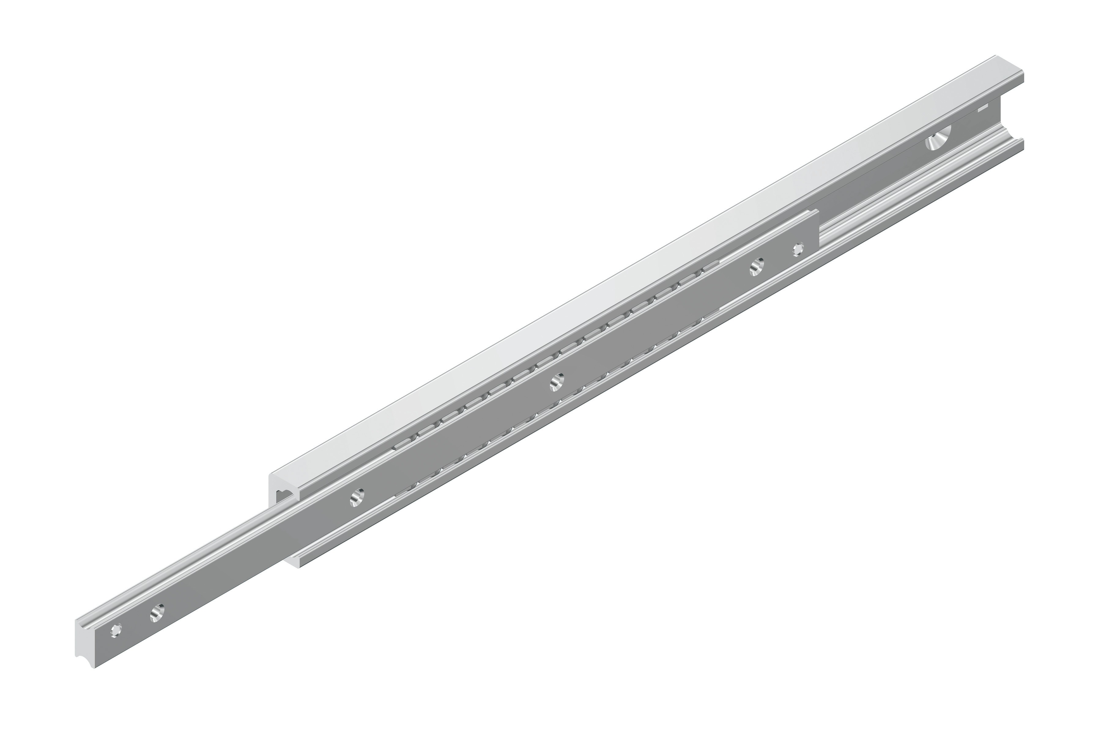
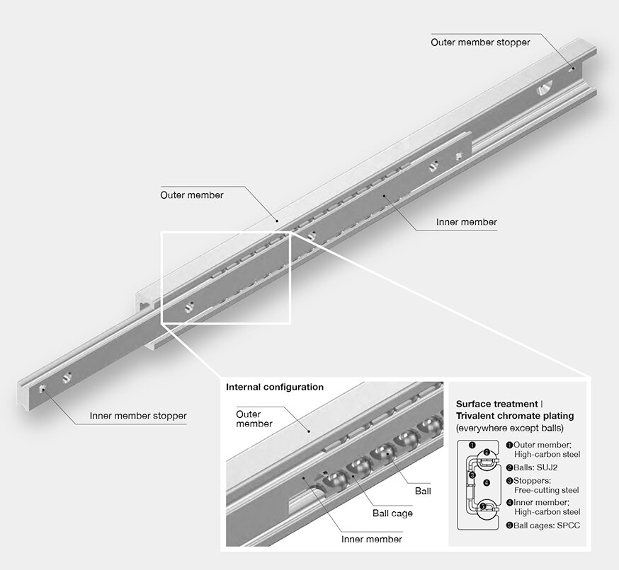
Structure and Features
To meet the needs of the logistics and railway industries, the Utility Slide ATG combines the benefits of conventionalslide rails with the technology THK cultivated with the LM Guide in order to improve the permissible load and extend the service life.
Improved Permissible Load and Extended Service Life
The Model ATG distinguishes itself from conventional slide rails by heat treating the outer and inner members to increase surface hardness and strength. The result is a high load capacity, high durability, and improved permissible load and service life compared to conventional products.
Easy to Install
The circular arc grooves make the Model ATG excel at adjusting to slight inaccuracies in the mounting surface during installation.
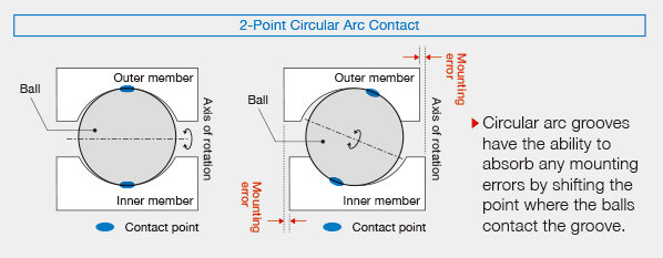
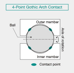
Helps Prevent Locking at the Stroke End
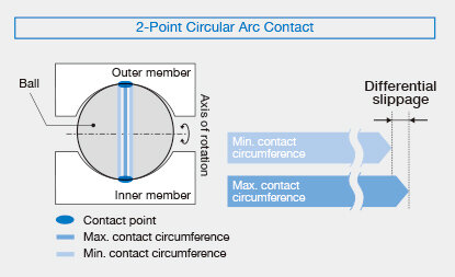
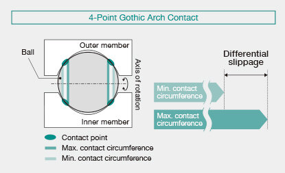
Since the Model ATG features circular arc grooves, it experiences less differential slippage than conventional (Gothic arch groove) products, which helps keep balls from becoming misaligned and causing the product to lock at the stroke end. This helps improve the stability of machine operations.
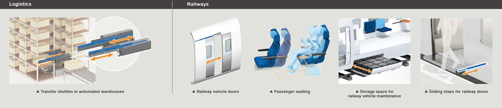
Applicable Fields
General Specifications
| Item | Unit | Model | |||
|---|---|---|---|---|---|
| ATG22S | ATG28S | ATG35S | ATG43S | ||
| Product width | mm | 22 | 28 | 35 | 43 |
| Permissible load*1 | N/set | 1,690 to 3,920 | 3,410 to 6,600 | 5,150 to 9,740 | 6,490 to 13,470 |
| Max. sliding resistance*2 | N | 3 | 5 | 5 | 5 |
| Operating temperature range*3 | ℃ | -15°C to 100°C | |||
| Grease | - | AFB-LF | |||
- 1. The permissible loads are the values for one set of two slide rails. They are calculated from the permissible surface pressure based on a load centered between the inner members.
- 2. When assembled, the balls are adjusted to aim for zero clearance and to keep the sliding resistance at or below the upper limit.
- 3. Contact THK if the product will be used in an environment outside of the specified temperature range.
Detailed information for each model number
Dimensional drawing/Dimensional table
THK Online Services
Member-Exclusive Content
These contents can be accessed
after registering as a member.
Benefit 1: Useful features
-
 Easy product comparisonsHighlight feature
 -
 Save items for laterreview Favorites feature
Benefit 2: Exclusive content
| Products | Contents |
|---|---|
| LM Guide | LM rail standard lengths and maximum length, tapped-hole type LM rail, frame for LM rail clamps, steel plate for LM rail clamps, etc. |
| Ball Screw | Axial clearance, maximum manufacturing length of shaft, etc. |
| Actuator | Movable part mass, etc. |