Pick and Place Robot PPR
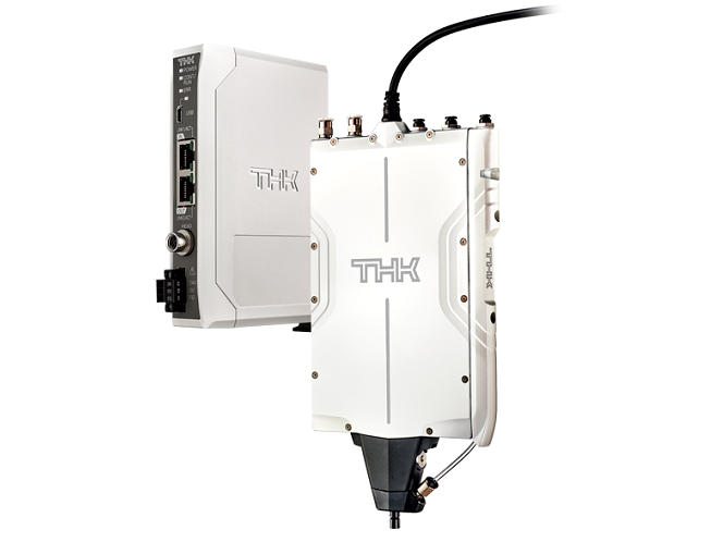
The PPR not only supports linear and rotary operation, but also has pneumatic devices and various sensors integrated.
The all-in-one robot combines all components required for optimized pick and place applications.

Features
Example Applications
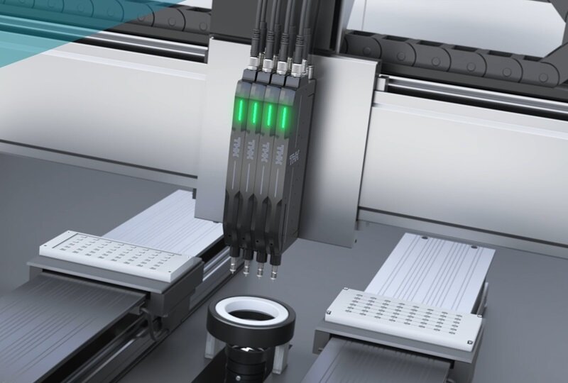
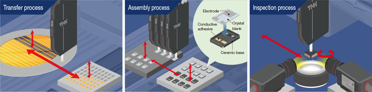
Transfer process
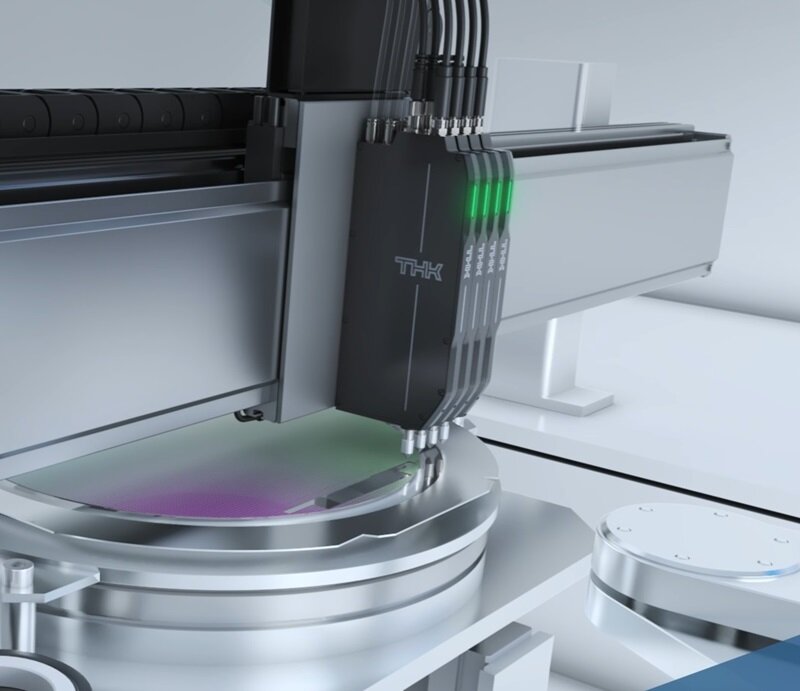
Assembly process
Features of PPR2-LR04
Providing both high-speed performance and accurate contact detection for the picking and placing operations
involved in automated transport, assembly, and
inspection of minute workpieces had its challenges.


Damage to workpieces
Unable to detect minute impacts at time o contact with workpiece due to detecting sliding resistance and external vibrations.

■ Example defect
-
Chipping 
-
Contact defect 
-
Contact defect Alignment defect 
-
Warping/
deflection
-
Internal crack 
-
Scratches/
debris
-
Slippage 
-
Scratches/
cracks
Pick and place speed
Control processing time is a limiting factor that dictates how much cycle times can be reduced.

Mechanism size
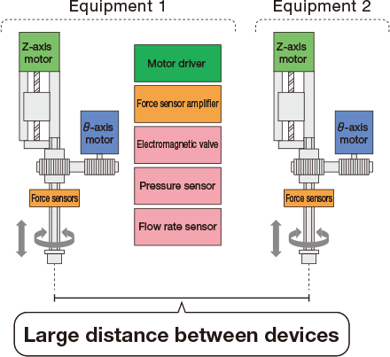
The more devices that are added to a machine, the larger it becomes, and when performing simultaneous transport, the distance between machines also gets larger.
Protect workpieces from damage and reduce cycle
times by using a Pick and Place Robot (PPR) with
force control.
Example applications
Reduced Workpiece Damage
THK's unique force-sensing technology detects contact between the nozzle and workpiece with a high degree of accuracy.
Minimum detection
0.15N
Reduced Cycle Time
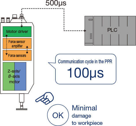
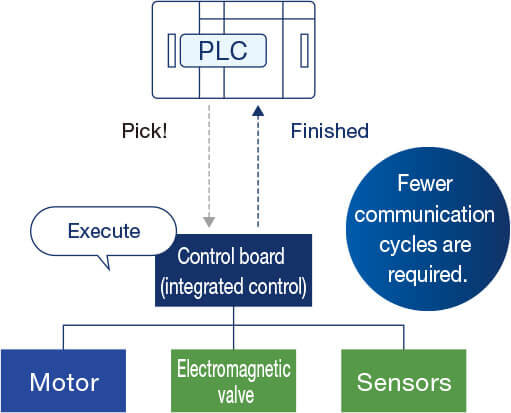
The PPR is compatible with sequence controls that integrate each motor and sensor. This requires fewer communication cycles and saves time when compared to conventional controls.
in the PPR
100μs
Compact Design
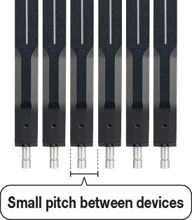
The head section is designed to be thin. Simultaneous transport is achieved by using multiple PPRs in a parallel array.
parallel array
15mm
Reduced Workpiece Damage
High-Precision Contact Force DetectionPatent pending
Conventional system
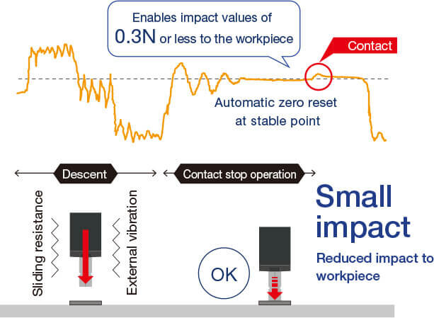
Unable to detect minute impacts at time of contact with workpiece due to detecting sliding resistance and external vibrations.

PPR series
The proprietary algorithm automatically resets the reference value to zero based on the average value from sliding resistance and external vibrations to detect impact at time of workpiece contact.
Integrated Control Enables Instant Stop upon ContactPatent pending
Conventional system
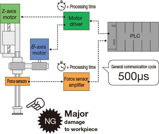
Cannot stop immediately after pressing force detection, leading to heavy damage to workpieces.
PPR series
Minimizes damage to workpieces because it can immediately stop after pressing force detection.
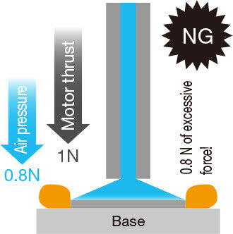
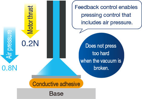
Application ExamplesExample: Does not press too hard when the vacuum is broken.
Conventional system
Contact defect
Current doesn’t flow due to crushing
PPR series
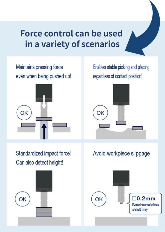
Switching to force control standardizes the pressing force applied to the workpiece (force sensor output is stabilized), reducing damage.

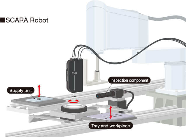
Configuration Examples

Reduced Cycle Time
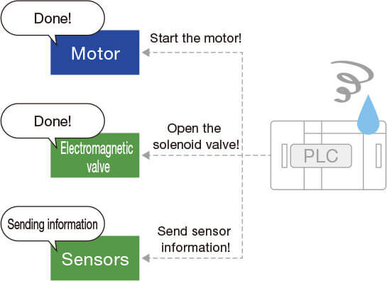
Integrated Control System Reduces Control TimePatent pending
Conventional system
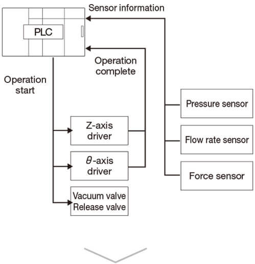
In a conventional system, the PLC controls everything.

This makes it difficult to adjust the timing of each device.
PPR series
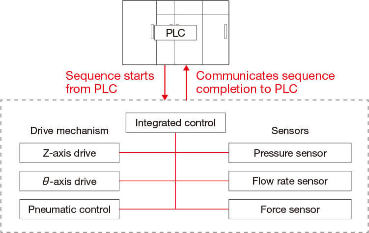
An internal control board provides integrated control of each unit.

Timing adjustment can be done with the waveform monitor.
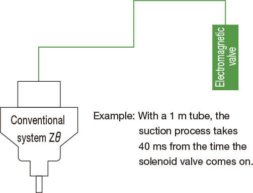
Reduce Pneumatic Routing with Integrated Solenoid Valves
Conventional system
In conventional devices, the solenoid valve is located away from the Zθ mechanism
It takes too long to complete the suction process.
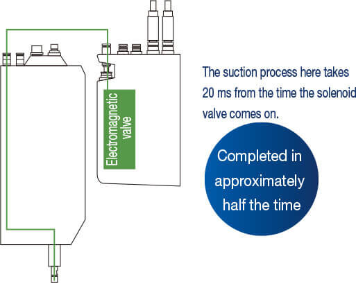
PPR series
The integrated solenoid valve allows for a shorter route to the shaft end.
This provides a short suction time.
Compact Design
Linear and Rotator Operations, Pneumatics, and Sensors All Included
Optimized for transport of minute workpieces.
Pick and place solution with simple installation and minimal wiring.

Can be Arrayed in a Series with a 15 mm Pitch
Transport multiple workpieces simultaneously with heads lined up in an array. Make efficient use of limited spaces with the PPR's thin design.

The head is even more compact on the PPR2.
A separate pneumatic unit offers a more compact design. Achieve shaft runout accuracy of 5 μm or less.
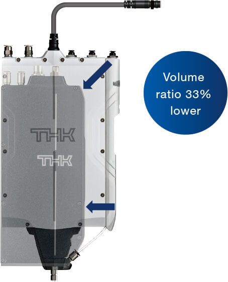

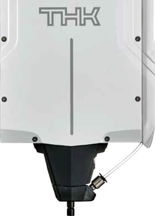
Features of PPR-LR3
Reduced workpiece damage
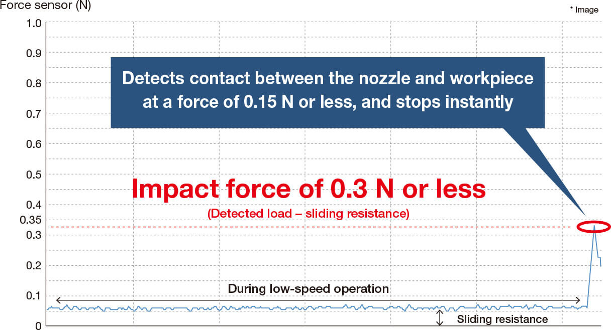
The force sensor provides instantaneous contact stop
THK's unique sensing technology detects minute forces when the workpiece comes into contact with the nozzle, which has conventionally been difficult.
The feedback control makes it possible to achieve both high-speed operation and reduced workpiece damage.
* Force sensor resolution: 0.01 N
Reduced cycle time
The integrated control system reduces time loss
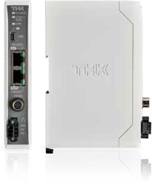
The PPR enables sequence control with each motor and sensor integrated. Compared to conventional PLC-based control, the number of communications is reduced and time loss is minimized.
Conventional system
All linked operations and timings are managed by PLC

PPR system
Linked operations and timings are completed with integrated control
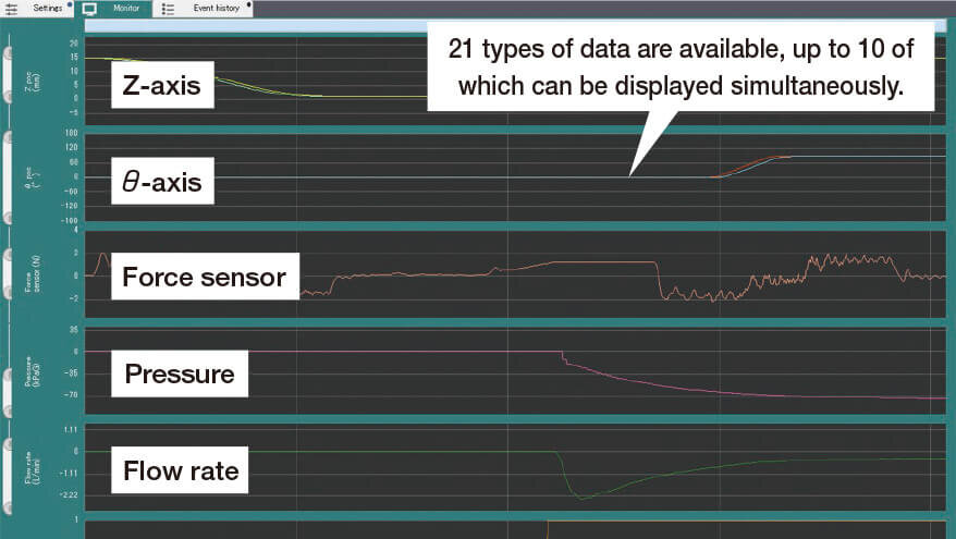
Visualizes the pick and place process
Setting/monitoring software "T-ACT"
Obtaining waveforms by monitor function
All sensor information can be monitored in waveform, including the force, pressure, flow rate, and position sensors.
The information is displayed for each pick-and-place cycle.
* CSV output is also available
Error logging function
Sensor information can be logged when an alarm occurs or at a specified timing.
Data at a sampling cycle of 0.1 ms can be acquired for a 10-second period.
* Data 8 seconds before and 2 seconds after alarm

Specifications
| Item |
PPR2-LR04
Small head model  |
PPR-LR3
Integrated pneumatic unit model  |
|||
|---|---|---|---|---|---|
| Head | Z-axis | Rated thrust1 | [N] | 4.0 | 3.3 |
| Maximum thrust1 | [N] | 8.6 | 5.6 | ||
| Load capacity | [g] | 80 | 80 | ||
| Maximum speed | [mm/s] | 500 | 500 | ||
| Stroke | [mm] | 20 | 30 | ||
| Resolution | [μm] | 1 | 1 | ||
| Positioning repeatability | [μm] | ±1 | ±1 | ||
| θ-axis | Rated torque1 | [mN・m] | 3.7 | 1.6 | |
| Maximum torque1 | [mN・m] | 9.4 | 5.2 | ||
| Maximum permissible inertia | [kg・mm2] | 2 | 2 | ||
| Maximum rotational speed | [rpm] | 1400 | 1400 | ||
| Resolution | [deg] | 0.01 | 0.01 | ||
| Runout accuracy | [μm] | 5 or less2 | 50 or less3 | ||
| Positioning accuracy | [deg/180deg] | 0.06 or less | 0.06 or less | ||
| Movable part inertia | [kg・mm2] | 0.1 | 0.1 | ||
| Mass | [g] | Approx.380 | Approx.620 | ||
| perating temperature/humidity | 0~40°C/20~80%RH(No freezing or condensation) | ||||
| Controller | Input power supply | [V] | DC24±10% | DC24±10% | |
| Power supply capacity | [A] | 4 | 4 | ||
| Mass | [g] | Approx.190 | Approx.190 | ||
| Supported networks | EtherCAT MECHATROLINK-III EtherNet/IP Ethernet(TCP/IP) |
||||
| Operating temperature/humidity | 0~50°C/90%RH or less(No freezing or condensation) | ||||
| Standards | CE | ||||
- 1 Values where the average armature winding temperature is 100°C. Values for other items assume a temperature of 20°C.
- 2 The value is measured with a dial gauge when the shaft is at its maximum extension (st: 20 mm).
- 3 Value with shaft at maximum extension (st: 30 mm).
