Jul 5, 2023
Dec 11, 2025
Products
The Pick and Place Robot (PPR): The Perfect Choice for Electronic Component Assembly

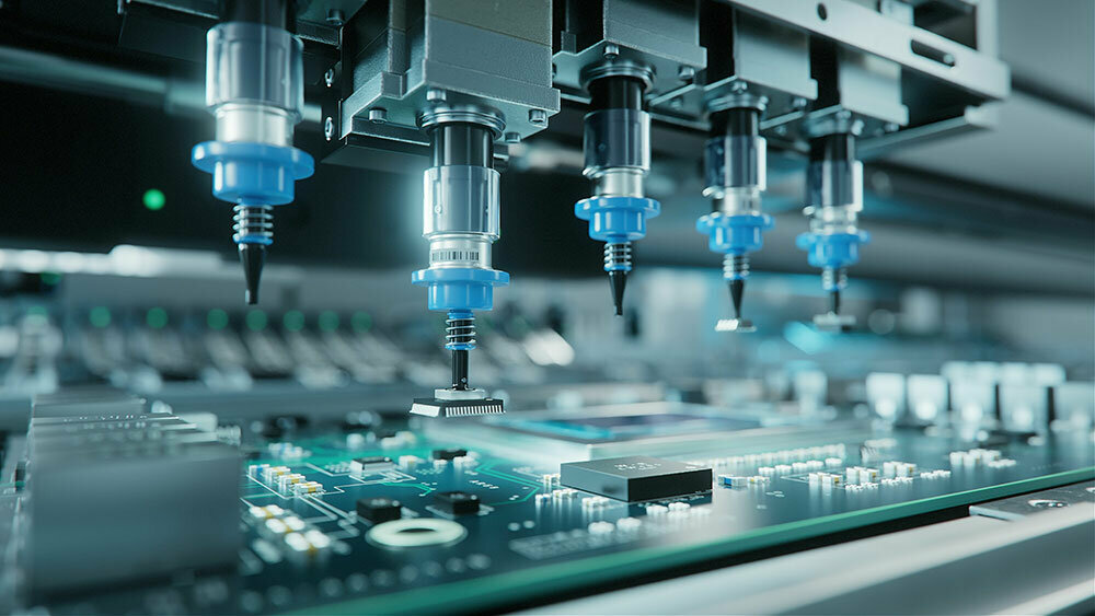
We're now in an age where every single thing you own—from smartphones and computers to household appliances and cars—contains electronic components. Everyone is probably familiar with the image of electronic components as circuits that move machinery, which are made by soldering components onto a green circuit board. But do you know just how small those components have become? Looking at typical components as an example, the smallest resistors and capacitors are 0201 size (0.2 mm × 0.1 mm). At this granular size, it's becoming difficult to pick them up even with tweezers. The smaller and thinner they get, the more difficult it becomes for production equipment to handle them, which causes a bottleneck in transfer processes.
In this article, we’ll take a look at how the Pick and Place Robot is optimized for assembling and transferring these kinds of tiny electronic components, which will include a rare peek inside the structure of this product.
The Pick and Place Robot
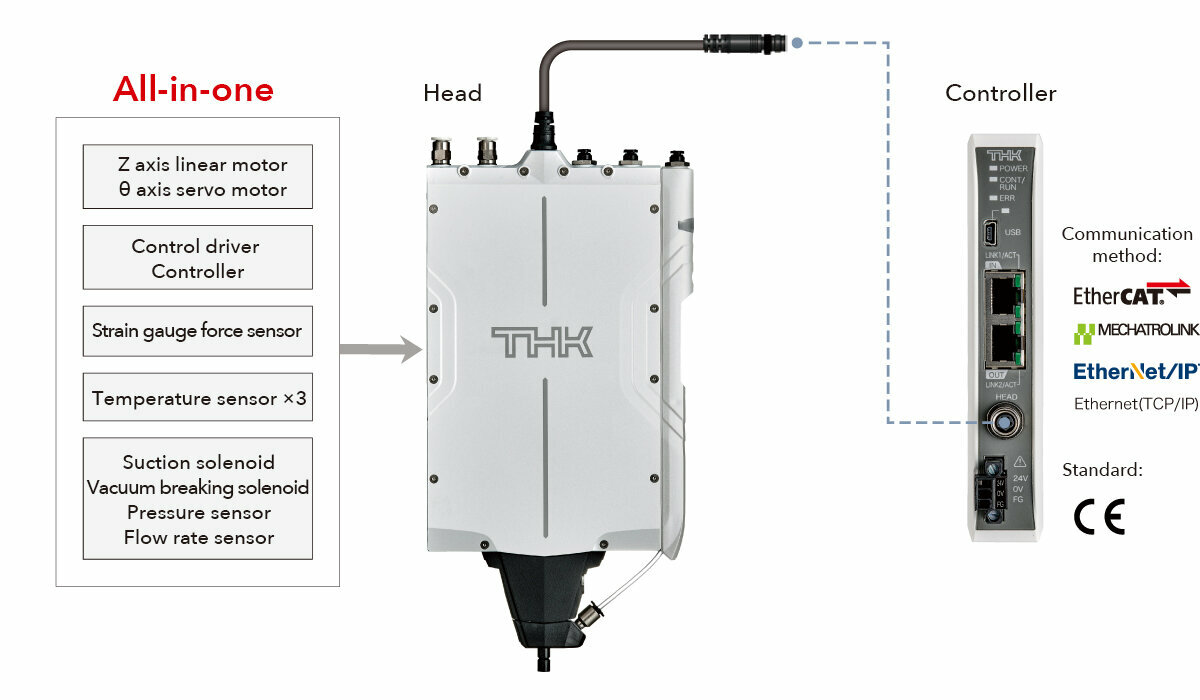
The Pick and Place Robot (PPR) is an all-in-one process-optimizing transfer tool that features all of the elements needed to pick and place small electronic components. The PPR autonomously executes a sequence of operations where it approaches at high speed, then gently contacts and adheres to the workpiece with vacuum suction before quickly lifting it. This has earned the PPR acclaim, and some customers have implemented the system in a wide variety of processes. However, even though the PPR has been on the market for three years, we have not fully introduced its special features. In this product blog, we’ll examine what the PPR is and discuss its special features and the applications where it is used, starting with what makes it an all-in-one system.

Structural Elements of the Main “Head” Unit for Vacuum Suction and Workpiece Transfer
When we've showcased the PPR workpiece suction and transfer demo at trade shows, a number of people have shared their impression that the head is big and the Z/θ unit is large compared to the stroke. That is why we decided to unveil the interior of this product. By revealing this secret, we hope you will gain an understanding of the reason why the head is large and what advantages that brings.
The PPR comes with a head, controller, and the cable that connects them. In this article, we will highlight the head portion, which is the main unit of the PPR.
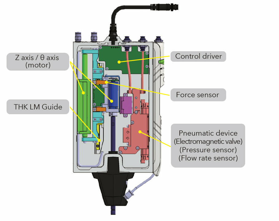
The PPR head has three parts built in: a Z axis/θ axis drive element, a pneumatic component for the vacuum suction, and the core control component.

1. Z Axis/θ Axis Drive Element
The Z axis uses a rod-type linear motor. An optical incremental encoder with a resolution of 1 μm is used as the position sensor. A built-in circuit board provides fully closed feedback control, enabling high-precision operations and a positioning repeatability of 1 μm. Travel accuracy is also ensured by the use of a THK LM Guide for the linear motion guide, which enables a maximum stroke of 30 mm.

The θ axis utilizes a brushless DC motor. An optical incremental encoder is used here as well, enabling high-precision positioning with a resolution of 0.01°. Thanks to its negative pressure structure, which will be discussed later, it bears no load from any rotary joint, and the air tubes do not become entangled. As a result, it can rotate more than 360°. The PPR’s output shaft is connected to the θ axis by a coupling, and the customer connects tools such as collets and suction pads that adhere to workpieces on the end of this shaft.
The force sensor is the most important part of the PPR. Located in the part that connects the Z axis and θ axis, this sensor detects the load acting on the shaft and θ axis motor on the movable output side in the Z axis direction. The force sensor has a resolution of 0.01 N and a measurement range of up to 10 N (between -3.5 and 6.5 N). It is utilized by the contact stop and pressing force control functions of the Z axis. As a typical example of how the sensor is used in practice, if the Z axis descends at a rate of 1 mm/s, it will stop when it detects a contact force of 0.15 N. Furthermore, once it has come in contact with the workpiece, it can maintain a pressing operation with a force of 1.0 N for a specified length of time. We’ll go over some concrete process improvement proposals utilizing the force sensor in a separate article.
The PPR has a built-in brake. If the actuator used in the Z axis direction does not have a mechanism to keep it from falling, then it will inevitably fall from its own weight once the power to the motor is shut off. If it falls, the suctioned workpiece could drop, the shaft could interfere with another axis, or it could lead to broken parts or other damage. To prevent this from happening when using linear motor actuators on the Z axis, people have often used a spring as part of a fall prevention mechanism, which would sometimes cause the system to rise suddenly and unexpectedly. At other times, it could cause slight drops when the servo for the motor was turned on. By having a built-in brake and force sensor, the PPR allows you to turn the servos that use these mechanisms on and off without causing the shaft to drop.
2. Pneumatic Structure for Vacuum Suction

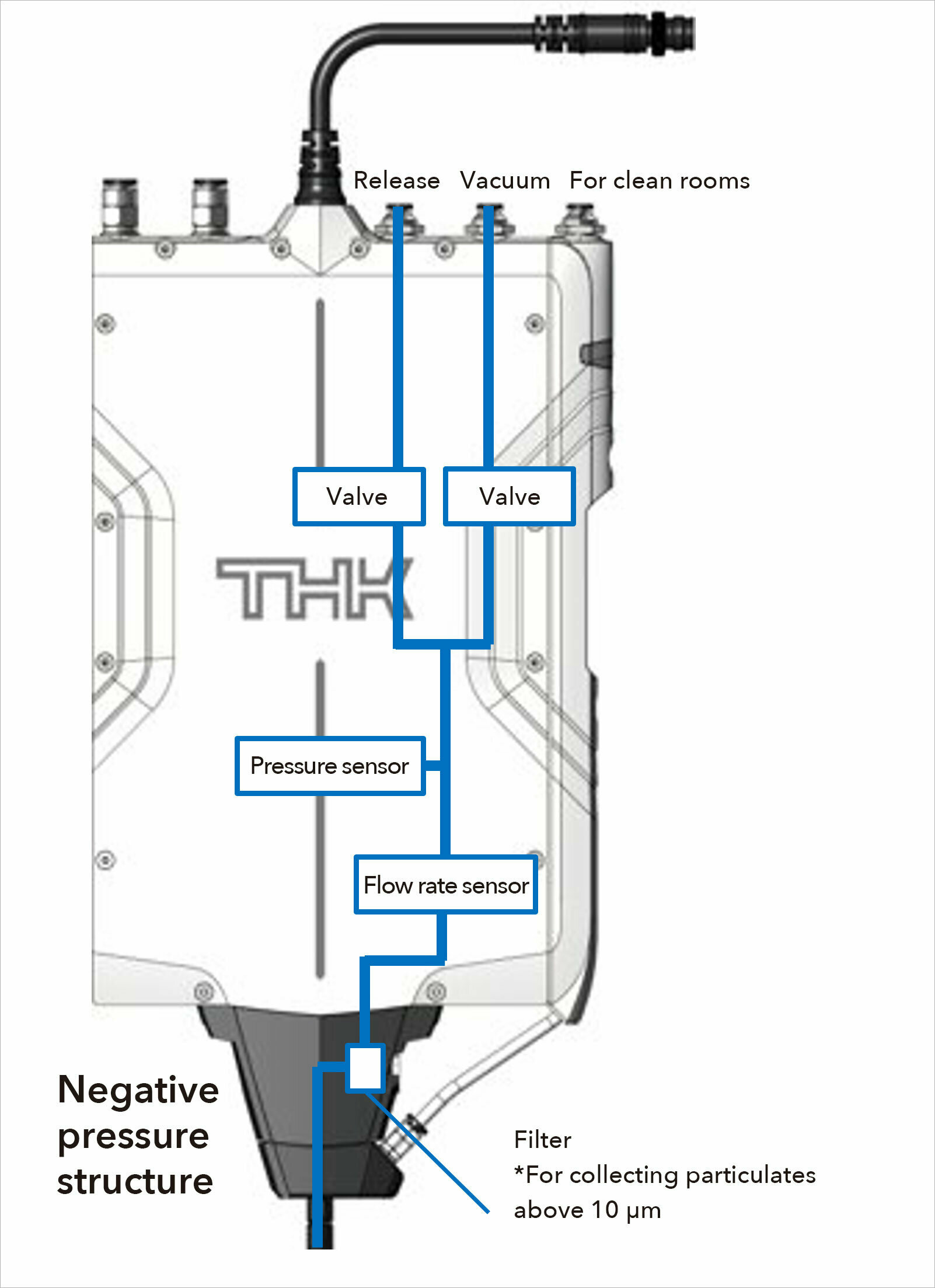
At the upper part of the main unit, there are five couplings for air piping. From the left, there are two air-cooling ports, then past the central pigtail cable, there's a positive pressure (release) port, a negative pressure (vacuum) port, and contamination suction port located on the cover on the far right.
The air-cooling ports are for cooling the main unit. The PPR is designed to be compatible with multiple stacked axes, so if the service conditions seem likely to cause the internal temperature to get too hot, you can use these ports to provide cooling air. You can cool the system by feeding air through the IN port on the left, then suctioning it out through the adjacent OUT port. Most customers currently using this product have not needed to provide cooling air, as there are times of rest during their regular transfer operations, such as during XY transfers.
The positive pressure (release) port and negative pressure (vacuum) port are connected to the pneumatic module on the right side of the main unit’s interior. This is a manifold that contains two electromagnetic valves (the suction valve and release valve), a pressure sensor, and a flow rate sensor. The pneumatic circuit is as shown on the right. In a traditional device structure, the electromagnetic valve is placed in a separate location from the nozzle tip, which means you have to factor in the time it takes air to arrive at the destination. That has made it difficult to perform timing adjustments. The advantage of using the internal piping of the PPR is that you can limitlessly minimize the spatial volume before the tip, thereby shortening the time it takes between turning the electromagnetic valve on and off and when the suction pressure occurs. This also makes it easy to perform adjustments that will shorten cycle times.
The black plastic component on the tip of the head is the negative pressure structure. This part connects the hollow interior of the shaft to the air circuit of the main unit. Having this structure means that the tubes don’t move in the Z or θ direction, and the tubes don't become entangled. A filter is built into this structure in order to protect the interior. This filter is easy to replace. In fact, the pneumatic module is also a replaceable component, so it can be swapped out by the customer.
Finally, the contamination suction port on the far right is there to prevent the escape of contaminants originating from the interior of the PPR. These contaminants largely consist of abrasion dust generated by friction between the negative pressure structure and shaft. The shaft itself is generally clean, as the surface is treated to reduce its friction resistance. However, if an even higher degree of cleanliness is required for the application, suctioning air through this port can reduce the volume of contaminants released. This cleaning port and the associated piping pass through the cover, so you can use the product with this structure removed if it’s unneeded.
3. Control circuit board
As we have seen, the head contains a lot of components. Traditionally, wires would be sticking out of these various elements, and you would have to connect them to a controlling driver and PLC. However, the PPR contains an internal circuit board to control these parts. This circuit board consists of the communication element that connects to the controller and the sequence controls that enable the Z axis motor and θ axis motor, encoder input, force sensor input, electromagnetic valve drive, pressure and flow rate sensor input, brake drive, and each element to work in tandem. The head is capable of high-frequency control and input/output at a rate of once every 100 μs. As a result, the contact stop function that uses the force sensor has excellent responsiveness, and it performs high-speed sequence control for coordinating each part. The controller communicates every 500 μs, and it receives instructions and transmits internal data with each cycle. The project data that customers create is saved in the controller, so the head receives that information constantly as it proceeds to the next step in the operation. In addition, the 500 μs communication cycle is directly connected to that of the controller and PLC so the PLC can also receive sensor data and other information from within the head at a high frequency.
As seen above, internalizing the control functions of the driver makes it possible to connect the head and controller by only one thin cable (consisting of a power and communication wire). This bending-resistant cable can be used without fear of breakage even when installed on moving parts of the equipment.
Creating Convenience for Customers with the PPR
In this article, we've highlighted what goes into the PPR's all-in-one system. By combining these various elements, the PPR makes it possible to execute high-speed movements with the Z axis linear motor, control contact stops and pressing force through feedback from the force sensor, change the vacuum state through electromagnetic valves, judge workpiece suction through pressure and flow rate sensors, and perform alignment adjustments on the θ axis all at once.
If a customer were to create this same combination of components on their own, it would take an extensive amount of time to select the parts, make adjustments, and handle the programming. Because the PPR is an all-in-one tool, it both optimizes the customer's actual manufacturing processes and generates convenience for them. We hope more customers will get to know the PPR and be able to optimize their processes and achieve greater work efficiency.
In the next article, we’ll take a look at a specific example of how this product was adopted in a crystal oscillator manufacturing process.
Contact information
THK LM SYSTEM Pte. Ltd.
38 Kaki Bukit Place LM Techno Building Singapore 416216
Tel: +65-6884-5500 / Fax:+65-6884-5550
E-Mail:sales@thksg.com