May 22, 2024
Products
Optimal for Suction Transfer Processes in Crystal Oscillator Manufacturing! The Functionality of the Pick and Place Robot
In this article, we'll take a look at an example application of the Pick and Place Robot PPR introduced in our last post as it is utilized in the crystal oscillator manufacturing process. We’ll explain what a crystal oscillator is in the first place; show what role the PPR plays in the suction transfer, assembly, and mounting processes; and propose process improvements made possible with the PPR's “all-in-one” nature.
See our previous post: Exclusive Look at the Internal Structure of the Pick and Place Robot (PPR)
What is a Crystal Oscillator?
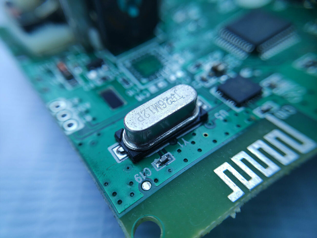
When you hear “crystal oscillator,” what comes to mind? Crystal oscillators are essential timing devices used in all sorts of electronic devices, from smartphones to computers. Think of them as being similar to a metronome, which you may remember from music class. A metronome can help us produce good music because it marks a constant tempo, neither speeding up nor slowing down. As you might have experienced, it's hard to keep to a set tempo when many people are playing music together.
Another place where we find crystal oscillators is in our clocks. In a quartz clock, the quartz serves as the crystal. Crystals produce a piezoelectric effect such that they can emit a signal at a set frequency when combined with a circuit and subjected to an electrical current. As a metronome is a reference for the tempo for music, the set frequency signal of a crystal oscillator serves as a reference for time.
The latest computer CPUs operate at clock speeds (the number of cycles a CPU executes in a second) measured in GHz. It might be hard to picture, but 1 GHz is like a metronome striking 1,000,000,000 beats per second. Crystal oscillators are indispensable for accurately producing those kind of frequencies. If there’s a CPU chip mounted onto a board, it’s safe to assume there is also a crystal oscillator mounted onto it as well.
* While this explanation of timing devices is limited to crystal oscillators as a representative example, other kinds of timing devices exist as well.

Structure and Manufacture of Crystal Oscillators
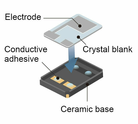
The structure of a crystal oscillator typically looks something like the image below.
As mentioned above, crystals produce a piezoelectric effect, meaning that they change shape when subject to an electric current, so the space around them needs to be empty. A crystal blank is set onto two or four points where electrically conductive adhesive has been applied to a base so that the center of the blank is raised, and a cover is placed over it. This is the general structure of a crystal oscillator.
Crystal oscillator assembly can largely be divided into two processes.
- Organizing, transferring, and conveying components
- Bonding the crystal blank and cover
Some of the difficulties involved in the assembly process include taking measures to ensure that the ceramic base, crystal blank, and cover don’t absorb the force of an impact and that the components aren’t pushed onto the adhesive with too much or too little force. While we believe that the PPR demonstrates its true value on both fronts, in this post we’re going to dig deeper into the bonding process.
The main flow of the bonding process is as follows.
- A set amount of adhesive is applied.
- The workpiece is picked up from a tray, a camera checks its positions and angles, and the position is corrected.
- The workpiece is mounted precisely to its installation position.
- Heat or ultraviolet light is applied to harden the adhesive.
Setting Components onto Adhesive
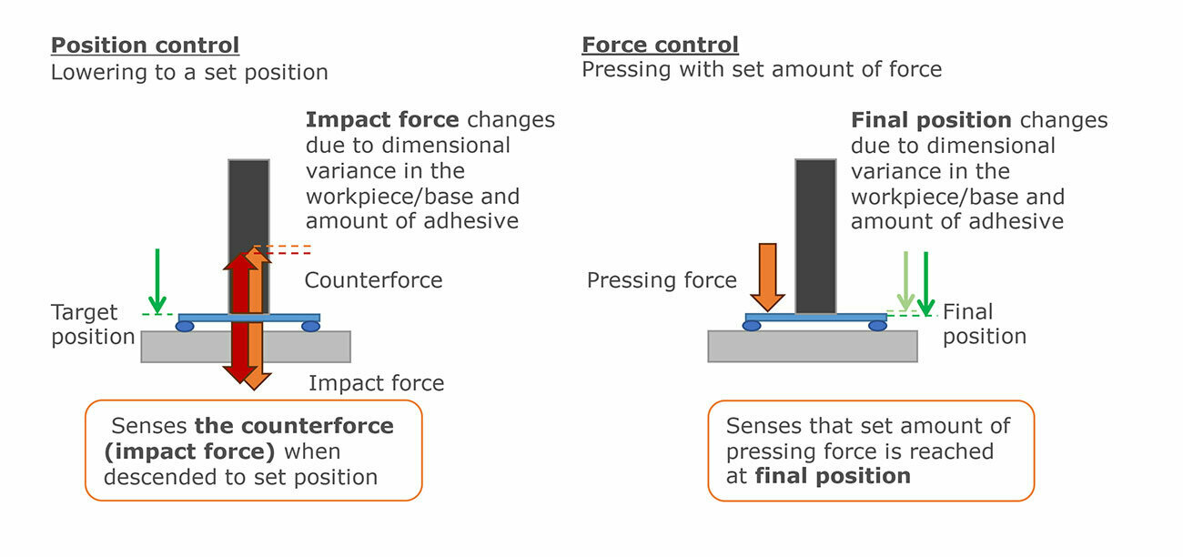
In the third step of the process above, when the workpiece is mounted precisely to its installation position, the Z axis needs to either move down to a set height or press down with a set amount of force.
Traveling down to a set height involves positioning control that utilizes position information from an encoder to stop at precisely the desired location. This is a normal motion that even conventional devices can produce.
But what kind of problems can arise when this process is actually performed?
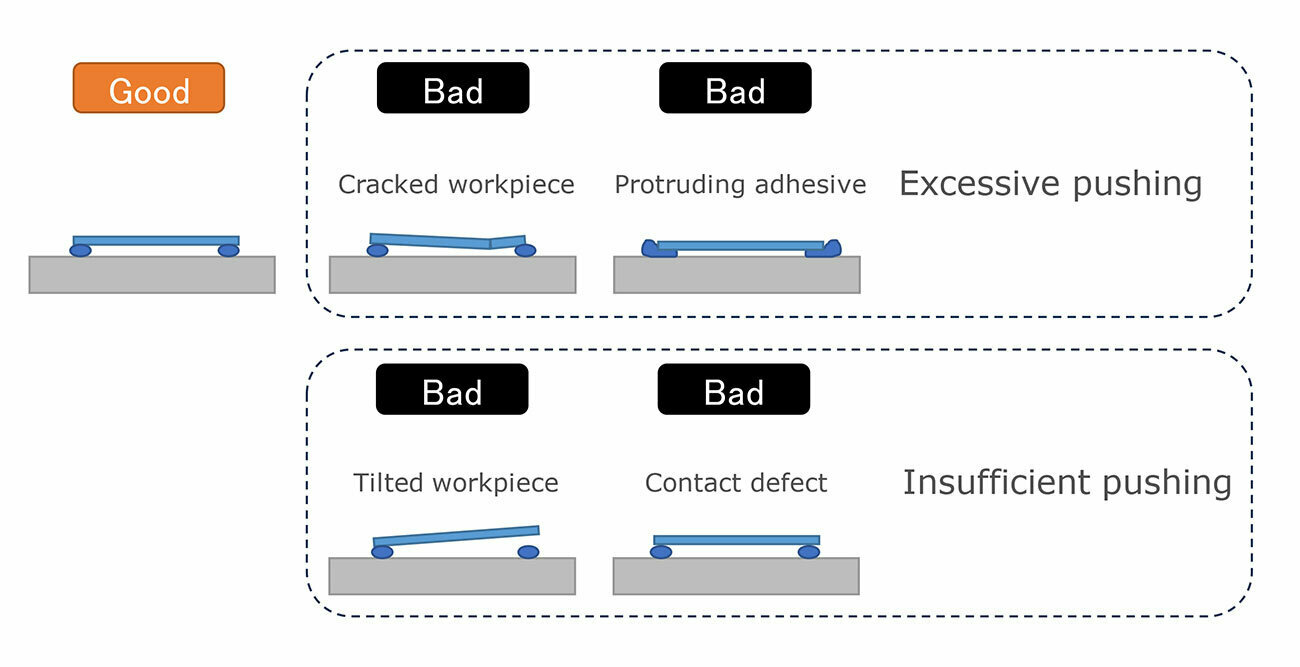
Ideally, the workpiece is placed in exactly the right location at the right angle, height, and orientation. In reality, though, variations in workpiece thickness and base height can create either too much or too little clearance. Additionally, because the adhesive is a fluid, it's difficult to strictly control how it behaves, which can create discrepancies in the amount of adhesive and how it is applied to a surface. When these issues occur, they can cause the kind of defects shown below.
Pushing down with excessive force causes:
-
Damage to the workpiece and base
- Adhesive protruding out from under the workpiece (causing conductivity defects and short circuiting)
Pushing down with insufficient force causes:
-
Bonding defects
- Tilted workpieces
Preventing defects from occurring or escaping undetected is crucial for improving the quality of finished products, but doing both is challenging in the context of an automated system.
Using the PPR System
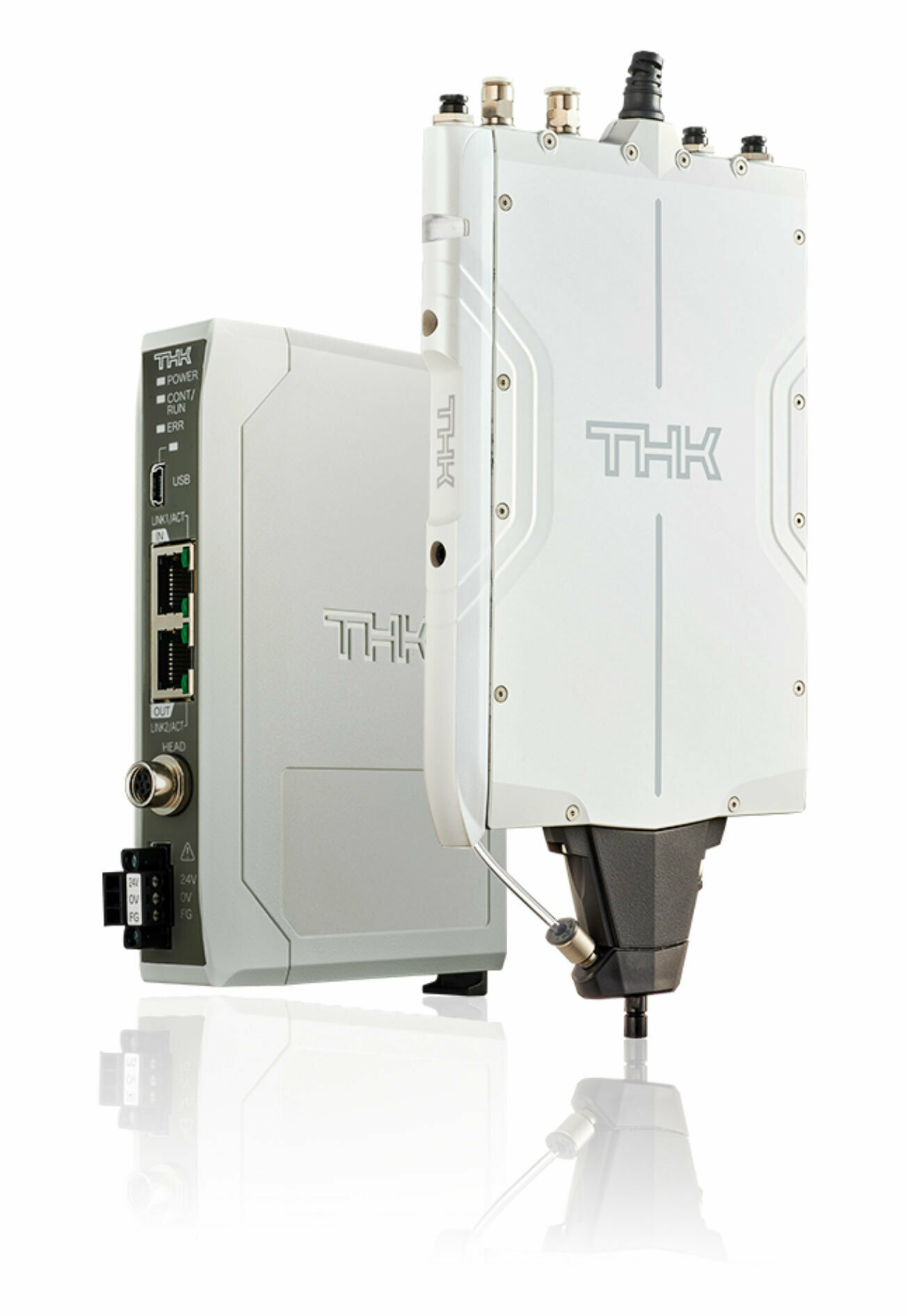
As an all-in-one system, the PPR has both a linear motor and an encoder for the Z axis as well as a force sensor all built in. For applications that require descending to a set height, the PPR provides positioning control by way of the encoder’s position feedback control. By reading the values from its built-in force sensor, it can also detect the counterforce acting on the shaft (i.e. the force applied to the workpiece) when it has descended to a set height. This constitutes a form of process monitoring and serves to prevent defects from escaping notice.
The PPR is also capable of performing this pressing operation at a set force with precision. Using values from the force sensor as feedback, it can control the amount of force being exerted, making it possible to press down on the adhesive with a set amount of force regardless of dimensional variance from the workpiece or base, even if too much or too little adhesive has been applied. Information about the position at which the press operation is complete can simultaneously be obtained from positioning information stored in the encoder. This reduces the occurrence of defects.
Optimizing the Bonding Process for Component Assembly
In this article, we focused on improvements for the bonding process utilizing the Pick and Place Robot PPR using crystal oscillators as an example application. To see more concretely what the PPR is capable of, see the video below, where it is installed onto a machine for a test. A waveform of the picking operation is available as well.
Insights from the PPR Waveform Monitor (THK Website)
There are many components that use adhesive bonding beyond crystal oscillators, and the PPR can contribute to quality and process improvements in their manufacture as well. Please don’t hesitate to contact THK if you are interested. We would be thrilled to help you make improvements to your processes.
Contact information
THK LM SYSTEM Pte. Ltd.
38 Kaki Bukit Place LM Techno Building Singapore 416216
Tel: +65-6884-5500 / Fax:+65-6884-5550
E-Mail:sales@thksg.com