LM Stroke Die-setting Ball Cage Models KS and BS
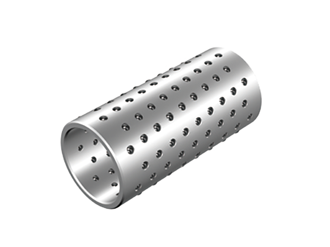
With models KS and BS, a large number of precision steel balls (sphericity in mutual difference: 0.0005 mm) compliant with JIS B 1501 are incorporated in a lightweight, highly rigid ball cage. The balls are arranged along the circumference of the ball cage in spirals so that the ball raceways do not overlap with each other. It enables these models to be used over a long period without wear and to demonstrate high durability.
Types
Highlight feature tags
- High accuracy
- Die-setting
- High accuracy
- Die-setting
Basic load rating kN : Basic dynamic load rating 10.3 to 22.5 / Basic static load rating 3.82 to 10.9
Features
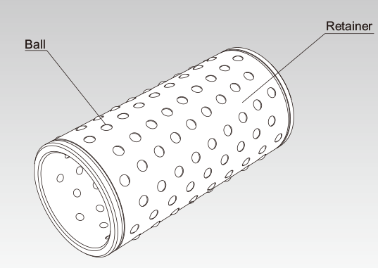
Structure and Features
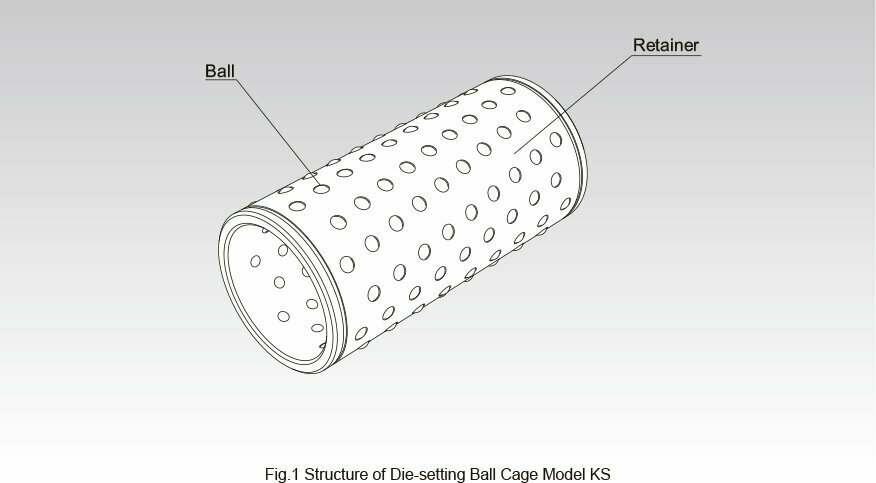
With models KS and BS, a large number of precision steel balls (sphericity in mutual difference: 0.0005 mm) compliant with JIS B 1501 are incorporated in a lightweight, highly rigid ball cage. The balls are arranged along the circumference of the ball cage in spirals so that the ball raceways do not overlap with each other. It enables these models to be used over a long period without wear and to demonstrate high durability. In addition, the ball pockets, which hold the balls, are finished with precision and continuously caulked with a unique process, enabling them to prevent the balls from falling. It allows the system to travel smoothly even if the ball cage is longer than the housing. These ball cages are used in precision press die set, spinning and weaving machine, precision measuring instrument, automatic recorder, medical equipment and various machine tools.
Rated Load and Service Life
The rated loads of models KS and BS are indicated in the respective specification tables. Their service lives are obtained using the service life equation for LM Stroke model ST on Rated Load and Nominal Life .
Fit
When using the Die-setting Ball Cage in the guide unit of the guide post of a precision press die set, normally select a negative clearance in order to increase the accuracy and the ball cage rigidity. Table1 shows typical fitting between the hole and the shaft. Select a combination of a hole and a shaft so that the clearance does not exceed the tolerance value of the radial clearance indicated in the specification table.
| Tolerance in hole dimensions: D | K5 |
|---|---|
| Dimensional tolerance of the shaft: d | h5 |
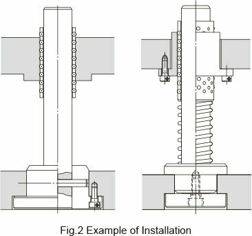
Installation of the Ball Cage
Fig.2 shows examples of mounting the Die-setting Ball Cage.
Detailed information for each model number
Dimensional drawing/Dimensional table
THK Online Services
Member-Exclusive Content
These contents can be accessed
after registering as a member.
Benefit 1: Useful features
-
 Easy product comparisonsHighlight feature
 -
 Save items for laterreview Favorites feature
Benefit 2: Exclusive content
| Products | Contents |
|---|---|
| LM Guide | LM rail standard lengths and maximum length, tapped-hole type LM rail, frame for LM rail clamps, steel plate for LM rail clamps, etc. |
| Ball Screw | Axial clearance, maximum manufacturing length of shaft, etc. |
| Actuator | Movable part mass, etc. |
Model Number Coding
THK Online Services
Member-Exclusive Content
These contents can be accessed
after registering as a member.
Benefit 1: Useful features
-
Easy product comparisonsHighlight feature
-
Save items for laterreview Favorites feature
Benefit 2: Exclusive content
| Products | Contents |
|---|---|
| LM Guide | LM rail standard lengths and maximum length, tapped-hole type LM rail, frame for LM rail clamps, steel plate for LM rail clamps, etc. |
| Ball Screw | Axial clearance, maximum manufacturing length of shaft, etc. |
| Actuator | Movable part mass, etc. |