Permissible Load and Mounting Orientation
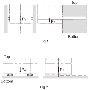
For use other than with the mounting orientation shown in Fig.1 , contact THK.
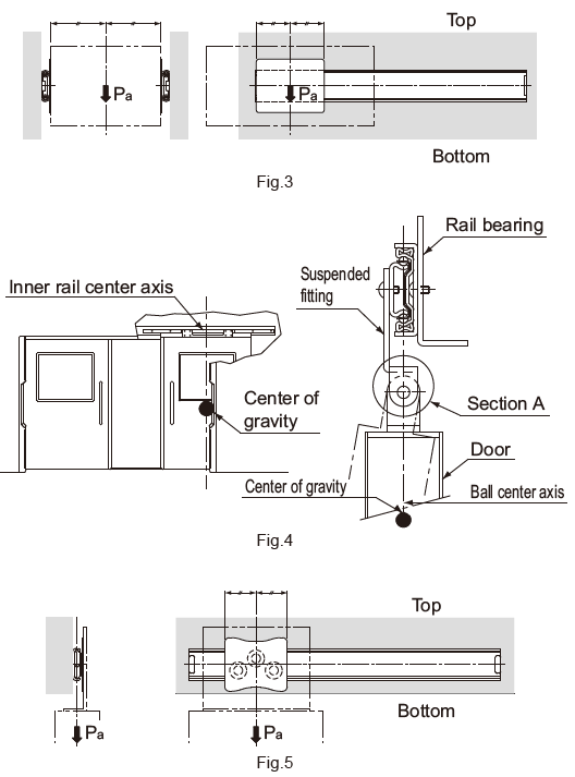
The permissible load of the Slide Rail indicates the load in the direction Pa that two rails can receive in the middle of the inner rail length at the maximum stroke.
The mounting orientation shown in Fig.2 is applicable to model FBL35B only.
The mounting orientation of Fig.3 is applicable to model FBL35F.
The mounting orientation of Fig.4 must be used for model FBL48DR. To prevent a moment load from being applied, position the center of gravity of the door on the ball and cage center lines, and ensure that section A of the hanger is structured to allow free rotation.
The mounting orientation of Fig.5 is applicable to model E36RS.
Unlike other slide rails, model FBL48DR and model E36RS are used in a single rail configuration.
Therefore, the load must be centered on the ball and the cage center line.