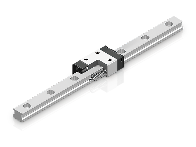
LM Guide
The LM Guide is our flagship product, the world's first practical application of rolling linear motion parts. It achieves higher precision, higher rigidity, reduced labor, higher speed, and longer service life of machines.
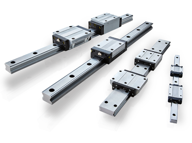
Types
Search products by various conditions
Features
| Functions Required for Linear Guide Surface | |
| Large permissible load | Smooth motion with no clearance |
| Highly rigid in all directions | Superbly high speed |
| High positioning repeatability | Easy maintenance |
| Running accuracy can be obtained easily | Can be used in various environments |
| High accuracy can be maintained over a long period | |
| Features of the LM Guide | |
| Large permissible load and high rigidity | |
| Accuracy averaging effect by absorbing mounting surface error | |
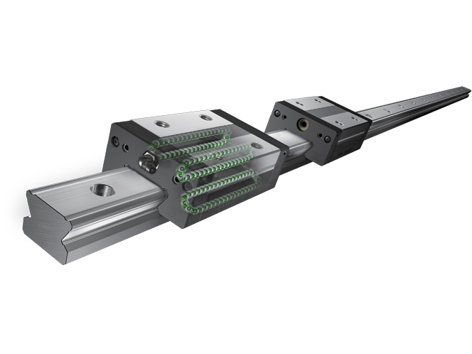
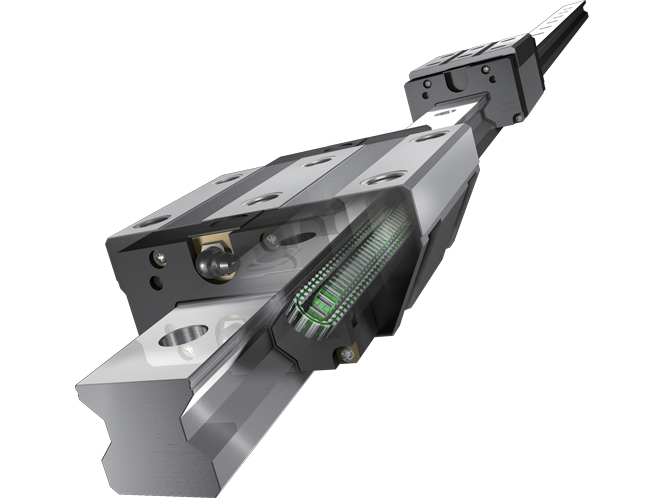
| Ideal four raceway, circular-arc groove, two point contact structure | |
| Superb error-absorbing capability with the DF design | |
| Low friction coefficient | |
| Wide array of options (QZ lubricator, Laminated contact scraper LaCS, etc.) | |
As a result, the following features are achieved.
Easy maintenance
Improved productivity of the machine
Substantial energy savings
Low total cost
Higher accuracy of the machine
Higher efficiency in machine design
Large Permissible Load and High Rigidity
Large Permissible Load
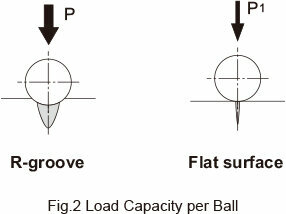
The LM Guide has raceway grooves with a radius almost equal to the ball radius, which is significantly different from the linear bushing. As shown in Fig.1 , which compares size between the LM Guide and the linear bushing with similar basic dynamic load ratings, the LM Guide is much smaller than the linear bushing, indicating that the LM Guide allows a significantly compact design.The reason for this space saving is the greater difference in permissible load between the R-groove contact structure and the surface contact structure. The R-groove contact structure (radius: 52% of the ball radius) can bear a load per ball 13 times greater than the surface contact structure. Since service life is proportional to the cube of the permissible load, this increased ball-bearing load translates into a service life that is approximately 2,200 longer than the linear bushing.
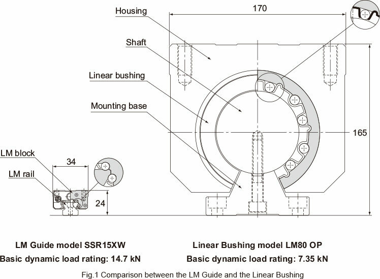
Permissible contact surface pressure: 4,200 MPa
|
Ball Diameter |
R-groove (P) |
Flat surface (P1) |
P/P1 |
|
φ 3.175(1/8") |
0.90 kN |
0.07 kN |
13 |
|
φ 4.763(3/16") |
2.03 kN |
0.16 kN |
13 |
|
φ 6.350(1/4") |
3.61 kN |
0.28 kN |
13 |
|
φ 7.938(5/16") |
5.64 kN |
0.44 kN |
13 |
|
φ 11.906(15/32") |
12.68 kN |
0.98 kN |
13 |
High Rigidity
The LM Guide is capable of bearing vertical and horizontal loads. Additionally, due to the circular-arc groove design, it is capable of carrying a preload as necessary to increase its rigidity.
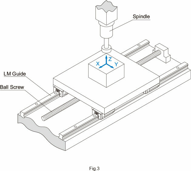
When compared with a feed screw shaft system and a spindle in rigidity, the guide surface using an LM Guide has higher rigidity.
Example of comparing static rigidity between the LM Guide, a feed screw shaft system and a spindle
(vertical machining center with the main shaft motor of 7.5 kW)
|
[Components] |
||
|
LM Guide |
: |
SVR45LC/C0 |
|
Ball Screw |
: |
BNFN4010-5/G0 |
|
Spindle |
: |
general-purpose cutting spindle |
|
Components |
X-axis direction |
Y-axis direction |
Z-axis direction |
|
LM Guide |
- |
2400 |
9400 (radial) 7400 (reverse radial) |
|---|---|---|---|
|
Ball screw |
330 |
- |
- |
|
Spindle |
250 |
250 |
280 |
- Note) The rigidity of the feed screw shaft system includes rigidity of the shaft end support bearing.
High Precision of Motion
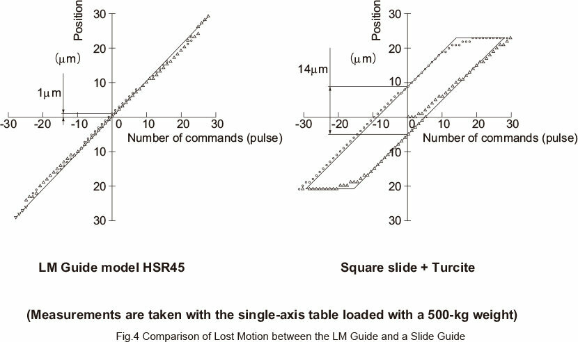
Small lost motion
The LM Guide is provided with an ideal rolling mechanism. Therefore, the difference between dynamic and static friction is minimal and lost motion hardly occurs.
|
Type |
Clearance |
Test method |
|||
|
As per JIS B 6330 |
Based on minimum unit feeding |
||||
|
10mm/min |
500mm/min |
4000mm/min |
|||
|
LM Guide (HSR45) |
C1 clearance(see table below) |
2.3 |
5.3 |
3.9 |
0 |
|---|---|---|---|---|---|
|
C0 clearance(see table below) |
3.6 |
4.4 |
3.1 |
1 |
|
|
Square slide +turcite |
0.02mm |
10.7 |
15 |
14.1 |
14 |
|
0.005mm |
8.7 |
13.1 |
12.1 |
13 |
|
|
Symbol |
C1 |
C0 |
|
Radial clearance |
-25 to -10 |
-40 to -25 |
|---|
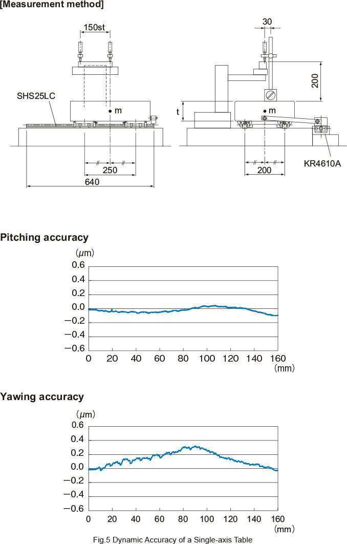
High running accuracy
Use of the LM Guide allows you to achieve high running accuracy.
High accuracy maintained over a long period
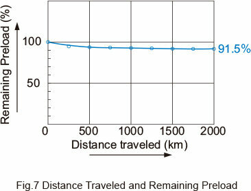
As the LM Guide employs an ideal rolling mechanism, wear is negligible and high precision is maintained for long periods of time. As shown in Fig.6 , when the LM Guide operates under both a preload and a normal load, more than 90% of the preload remains even after running 2,000 km.
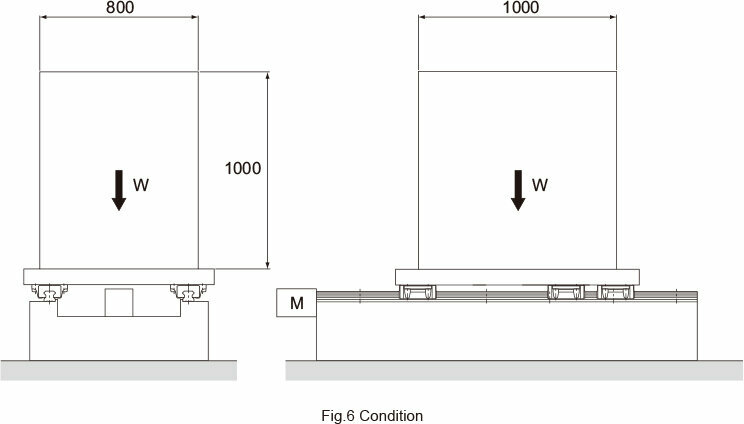
|
[Conditions] |
||
|
Model No. |
: |
HSR65LA3SSC0+2565LP-Ⅱ |
|
Radial clearance |
: |
C0 (preload: 15.7 kN) |
|
Stroke |
: |
1050mm |
|
Speed |
: |
15 m/min (stops 5 sec at both ends) |
|
Acceleration/decelelation time in rapid motion |
: |
300 ms (acceleration:α=0.833m/s2) |
|
Mass |
: |
6000kg |
|
Drive |
: |
Ball Screws |
|
Lubrication |
: |
Lithium soap-based grease No. 2 (greased every 100 km) |
Accuracy Averaging Effect by Absorbing Mounting Surface Error
The LM Guide contains highly spherical balls and has a constrained structure with no clearance.In addition, it uses LM rails in parallel on multiple axes to form a guide system with multiple-axis configuration. Thus, the LM Guide is capable of absorbing misalignment in straightness, flatness or parallelism that would occur in the machining of the base to which the LM Guide is to be mounted or in the installation of the LM Guide by averaging these errors.
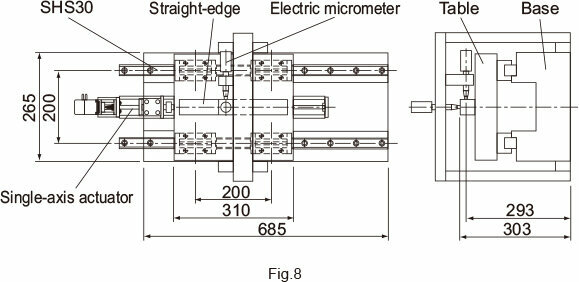
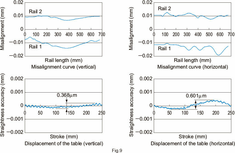
The magnitude of the averaging effect varies according to the length or size of the misalignment, the preload applied on the LM Guide and the number of axes in the multiple-axis configuration. When misalignment is given to one of the LM rails of the table as shown in Fig.8 , the magnitude of misalignment and the actual dynamic accuracy of the table (straightness in the horizontal direction) are as shown in Fig.9 .
By applying such characteristics obtained with the averaging effect, you can easily establish a guide system with high precision of motion.
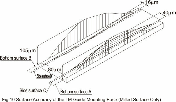
Even on a roughly milled mounting surface, the LM Guide drastically increases running accuracy of the top face of the table.
Example of Installation
When comparing the mounting surface accu -racy (a) and the table running accuracy (b), the results are :
|
Vertical |
92.5μm |
→ |
15μm |
= |
1/6 |
|
Horizontal |
28μm |
→ |
4μm |
= |
1/7 |
|
Direction |
Mounting surface |
Straightness |
Average (a) |
|
|
Vertical |
Bottom surface |
A |
80 |
92.5 |
|---|---|---|---|---|
|
B |
105 |
|||
|
Horizontal |
Side surface |
C |
40 |
28 |
|
D |
16 |
|||
|
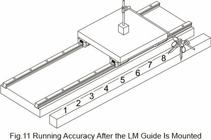
Direction |
Measurement point |
||||||||
|
1 |
2 |
3 |
4 |
5 |
6 |
7 |
8 |
Straightness (b) |
|
|
Vertical |
0 |
+2 |
+8 |
+13 |
+15 |
+9 |
+5 |
0 |
15 |
|---|---|---|---|---|---|---|---|---|---|
|
Horizontal |
0 |
+1 |
+2 |
+3 |
+2 |
+2 |
-1 |
0 |
4 |
Easy Maintenance
Unlike with sliding guides, the LM Guide does not incur abnormal wear. As a result, sliding surfaces do not need to be reconditioned, and precision needs not be altered. Regarding lubrication, sliding guides require forced circulation of a large amount of lubricant so as to maintain an oil film on the sliding surfaces, whereas the LM Guide only needs periodical replenishing of a small amount of grease or lubricant. Maintenance is that simple. This also helps keep the work environment clean.
Substantial Energy Savings
As shown in Table6 , the LM Guide has a substantial energy saving effect.
|
Machine Specifications |
||
|
Type of machine |
Single-axis surface grinding machine |
Three-axis surface grinding machine |
|---|---|---|
|
Overall length × overall width |
13m×3.2m |
12.6m×2.6m |
|
Total mass |
17000kg |
16000kg |
|
Table mass |
5000kg |
5000kg |
|
Grinding area |
0.7m×5m |
0.7m×5m |
|
Table guide |
Rolling through V-V guide |
Rolling through LM Guide installation |
|
No. of grinding stone axes |
Single axis (5.5 kW) |
Three axes (5.5 kW + 3.7 kW x 2) |
|
Table Drive Specifications |
Ratio |
||
|
Motor used |
38.05kW |
3.7kW |
10.3 |
|---|---|---|---|
|
Drive hydraulic pressure |
Bore diameter φ 160×1.2MPa |
Bore diameter φ 65×0.7MPa |
- |
|
Thrust |
23600N |
2270N |
10.4 |
|
Electric Power consumption |
38kWH |
3.7kWH |
10.3 |
|
Drive hydraulic pressure oil consumption |
400ℓ/year |
250ℓ/year |
1.6 |
|
Lubricant consumption |
60 ℓ/year (oil) |
3.6 ℓ/year (grease) |
16.7 |
Low Total Cost
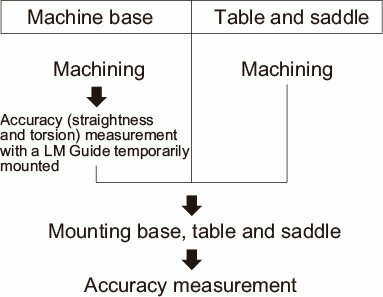
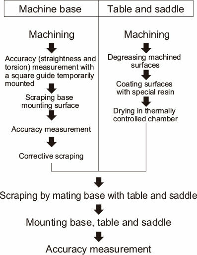
Compared with a sliding guide, the LM Guide is easier to assemble and does not require highly skilled technicians to perform the adjustment work. Thus, the assembly man-hours for the LM Guide are reduced, and machines and systems incorporating the LM Guide can be produced at lower cost. The figure below shows an example of difference in the procedure of assembling a machining center between using siding guides and using LM Guides.
Normally, with a sliding guide, the surface on which the guide is installed must be given a very smooth finish by grinding. However, the LM Guide can offer high precision even if the surface is milled or planed. Using the LM Guide thus cuts down on machining man-hours and lowers machining costs as a whole.
Assembly Procedure for a Machining Center
| Using LM Guides | Using Square Guides (Sliding Guides) |
 |
 |
When extremely high precision is not required (e.g., running accuracy), the LM Guide can be attached to the steel plate even if the black scale on it is not removed.
Ideal Four Raceway, Circular-Arc Groove, Two-Point Contact Structure
The LM Guide has a self-adjusting capability that competitors’ products do not have. This feature is achieved with an ideal four raceway, circular-arc groove, two-point contact structure.
Comparison of Characteristics between the LM Guide and Similar Products
| LM Guide: Four Raceway, Circular-arc Groove, Two-point Contact Structure |
Other Product: Two-row, Gothic-arch Groove Four Point Contact Structure |
|
LM Guide Model HSR 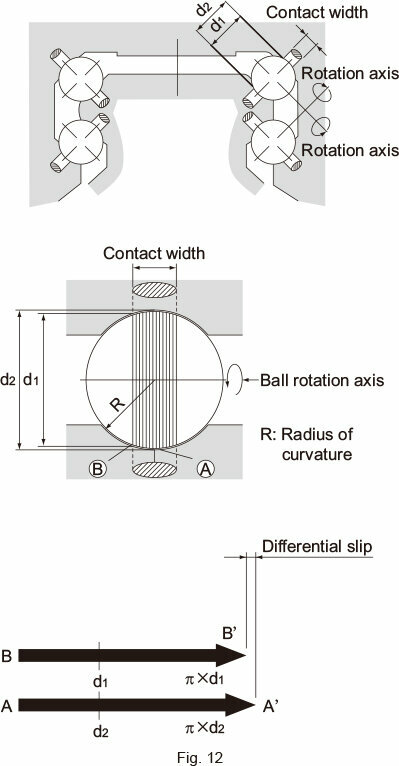 |
Two-row Gothic-arch groove product 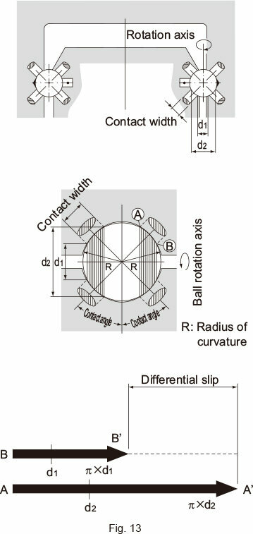 |
As indicated in Fig. 12 and Fig. 13 , when the ball rotates one revolution, the ball slips by the difference between the circumference of the diameter of inner surface (πd1) and that of the outer contact diameter (πd2). (This slip is called differential slip.) If the difference is large, the ball rotates while slipping, the friction coefficient increases more than 10 times and the friction resistance steeply increases.
|
LM Guide: Four Raceway, Circular-arc Groove, |
Two-Row, Gothic-Arch Groove, |
|
Smooth Motion |
|
|
Since the balls contact the raceway at two points in the load direction as shown in Fig. 12 and Fig. 13 whether under preload or normal load, the difference between d1 and d2 is small, as is the differential slip, allowing a smooth rolling motion. |
The difference between d1and d2in the contact area is large as shown in Fig. 12 and Fig. 13 .Therefore, if any of the following occurs, the ball will generate differential slip, causing friction almost as large as sliding resistance and shortening the service as a result of abnormal friction. |
|
Accuracy of the Mounting Surface |
|
|
In the ideal two-point contact structure, four rows of circular arc grooves are given appropriate contact angles. With this structure, a light distortion of the mounting surface would be absorbed within the LM block due to elastic deformation of the balls and moving of the contact points to allow unforced, smooth motion. This eliminates the need for a robust mounting base with high rigidity and accuracy for machinery such as a conveyance system. |
With the Gothic-arch groove product, each ball contacts the groove at four points, preventing itself from being elastically deformed and the contact points from moving (i.e., no self-adjusting capability). Therefore, even a slight distortion of the mounting surface or an accuracy error of the rail bed cannot be absorbed and smooth motion cannot be achieved. Accordingly, it is necessary to machine a highly rigid mounting base with high precision and mount a high precision rail. |
|
Rigidity |
|
|
With the two-point contact, even if a relatively large preload is applied, the rolling resistance does not abnormally increase and high rigidity is obtained. |
Since differential slip occurs due to the four-point contact, a sufficient preload cannot be applied and high rigidity cannot be obtained. |
|
Load Rating |
|
|
Since the curvature radius of the ball raceway is 51 to 52% of the ball diameter, a large rated load can be obtained. |
Since the curvature radius of the Gothic-arch groove has to be 55 to 60% of the ball diameter, the rated load is reduced to approx. 50% of that of the circular arc groove. |
|
Difference in Rigidity |
|
|
As shown in Fig.14 , the rigidity widely varies according to the difference in curvature radius or difference in preload. Curvature radius and rigidity 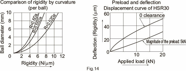 |
|
|
Difference in Service Life |
|
|
Since the load rating of the gothic arch groove is reduced to approx. 50% of that of the circular arc groove, the service life also decreases to 87.5%. |
|
Accuracy Error of the Mounting Surface and Test Data on Rolling Resistance
The difference between the contact structures translates into a rolling resistance.
In the gothic arch groove contact structure, each ball contacts at four points and differential slip or spinning occurs if a preload is applied to increase rigidity or an error in the mounting precision is large. This sharply increases the rolling resistance and causes abnormal wear in an early stage.
The following are test data obtained by comparing an LM Guide having the four raceway, circular-arc groove two-point contact structure and a product having the two-row, Gothic-arch, four-point contact structure.
[Sample]
| (1) |
LM Guide |
|
| SR30W (radial type) |
2 sets |
|
| HSR35A (4-way equal-load type) |
2 sets |
|
| (2) |
Two-row Gothic-arch groove product |
|
|
Type with dimensions similar to HSR30 |
2 sets |
[Conditions]
Radial clearance: ±0μm
Without seal
Without lubrication
Load: table mass of 30 kg
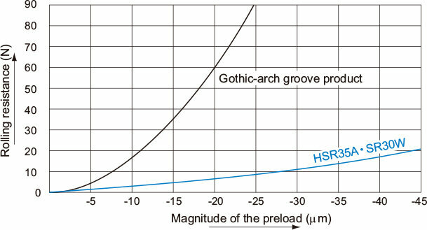
Data 1: Preload and rolling resistance
When a preload is applied, the rolling resistance of the Gothic-arch groove product steeply increases and differential slip occurs. Even under a preload, the rolling resistance of the LM Guide does not increase.
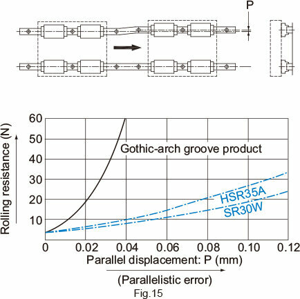
Data 2: Error in parallelism between two axes and rolling resistance
As shown in the Fig.15 , part of the rails mounted in parallel is parallelly displaced and the rolling resistance at that point is measured.
With the Gothic-arch groove product, the rolling resistance is 34 N when the parallelistic error is 0.03 mm and 62 N when the error is 0.04 mm. These resistances are equivalent to the slip friction coefficients, indicating that the balls are in sliding contact with the groove.
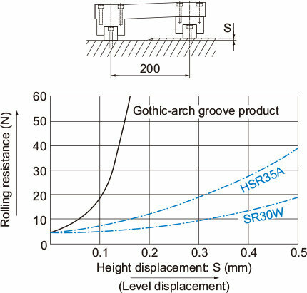
Data 3: Difference between the levels of the top and bottom rails and rolling resistance
Displace the bottom of either rail vertically by S and create the height difference between the two axes. Then, measure the rolling resistance. If there is a height difference between the rails, moment will act on the LM block. If the LM Guide’s groove is the Gothic-arc groove, this will cause spinning. The LM Guide with the circular-arc groove is capable of absorbing the error caused by the height difference between rails as great as 0.3/200 mm, where its rolling resistance will not increase significantly.
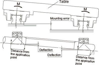
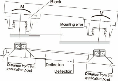
Superb Error-Absorbing Capability with the DF Design
Since the LM Guide has a contact structure similar to the front-to-front mount of angular ball bearings, it has superb self-adjusting capability.
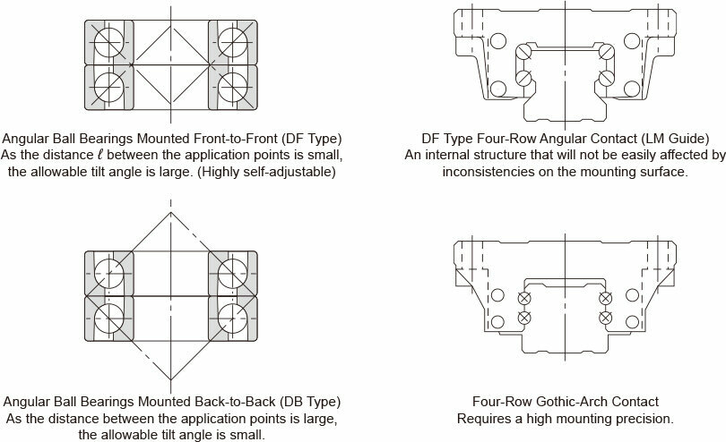
An LM ball guide mounted on a plane receives a moment (M) due to an error in flatness or in level or a deflection of the table. Therefore, it is essential for the guide to have self-adjusting capability.
|
LM Guide Model HSR |
Similar Product of a Competitor |
 |
 |
|
Since the distance between the application points of the bearings is small, the internal load generated from inconsistencies in the mounting surface is small, allowing movement to remain smooth. |
Since the distance from the application point of the bearing is large, the internal load generated from a mounting error is large and the self-adjusting capability is small.With an LM ball guide having angular ball bearings mounted back-to-back, if there is an error in flatness or a deflection in the table, the internal load applied to the block is approx. 6 times greater than that of the front-to-front mount structure and the service life is much shorter. In addition, the fluctuation in sliding resistance is greater. |