LM Guide Actuator
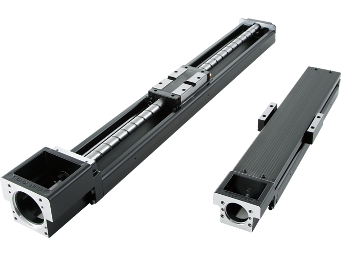
The LM Guide actuator is a highly rigid, highly accurate, and compact actuator that integrates an LM Guide and ball screw.
Using the LM Guide actuator can reduce the number of parts and the time required for equipment design.
Types
Features
Structure and Features

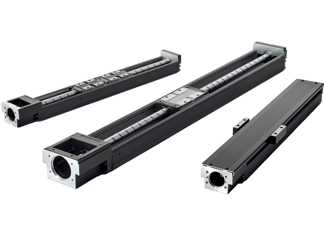
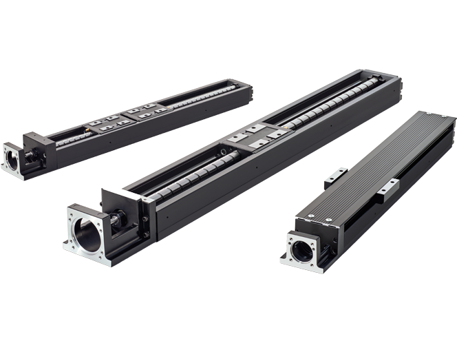
Caged Ball LM Guide Actuator Model KR and Model SKR are a compact actuators that have an inner block, which is a combination of an LM block and ball screw nut, inside a U-shaped outer rail.
In addition, by using ball cages in the LM Guide units and the ball screw unit, the Model SKR achieves high speeds, low noise, and long-term maintenance-free operation superior to the conventional Model KR. (A ball cage is used only for the LM Guide section of models SKR20 and SKR26 and the ball screw is fitted with a QZ Lubricator.)
Four-Way Equal Load
Each row of balls is arranged at a contact angle of 45° so that the load rating on the inner block is uniform in the four directions (radial, reverse-radial, and lateral directions), enabling the Model KR and Model SKR to be used in any mounting orientation.

High Accuracy
Since the linear guide consists of four rows of circular-arc grooves that enable balls to move smoothly with two points of contact even under a preload, a highly rigid guide with no clearance is achieved. Additionally, variation in frictional resistance caused by load fluctuation is minimized, allowing highly accurate feeding. The system contributes significantly to increasing precision and quality by providing precision-grade positioning performance to all kinds of machines.

High Rigidity
Use of an outer rail with a U-shaped cross section increases the rigidity against a moment and torsion.

|
Model No. |
IX (mm4) |
IY (mm4) |
Mass (kg/m) |
|---|---|---|---|
|
SKR20 |
6.0 × 10³ |
6.14 × 10⁴ |
2.6 |
|
SKR26 |
1.66 × 10⁴ |
1.48 × 10⁵ |
3.9 |
|
SKR33 |
5.35 × 10⁴ |
3.52 × 10⁵ |
6.1 |
|
SKR46 |
2.05 × 10⁵ |
1.45 × 10⁶ |
12.6 |
|
SKR55 |
2.07 × 10⁵ |
2.09 × 10⁶ |
13.2 |
|
SKR65 |
4.51 × 10⁵ |
5.73 × 10⁶ |
22.1 |
|
KR15 |
9.08 × 10² |
1.42 × 10⁴ |
1.04 |
|
KR20 |
6.1 × 10³ |
6.2 × 10⁴ |
2.6 |
|
KR26 |
1.7 × 10⁴ |
1.5 × 10⁵ |
3.9 |
|
KR30H |
2.7 × 10⁴ |
2.8 × 10⁵ |
5.0 |
|
KR33 |
6.2 × 10⁴ |
3.8 × 10⁵ |
6.6 |
|
KR45H |
8.4 × 10⁴ |
8.9 × 10⁵ |
9.0 |
|
KR46 |
2.4 × 10⁵ |
1.5 × 10⁶ |
12.6 |
|
KR55 |
2.2 × 10⁵ |
2.3 × 10⁶ |
15.0 |
|
KR65 |
4.6 × 10⁵ |
5.9 × 10⁶ |
23.1 |
lX = geometric moment of inertia around X axis
lY = geometric moment of inertia around Y axis
