Studying the Spline Shaft Strength
The spline shaft of the Ball Spline is a compound shaft capable of receiving a radial load and torque.
When the load and torque are large, the spline shaft strength must be taken into account.
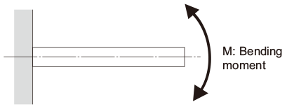
Spline Shaft Receiving a Bending Load
When a bending load is applied to the spline shaft of a Ball Spline, obtain the spline shaft diameter using the equation (1) below.
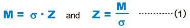
| M | Maximum bending moment acting on the spline shaft (N・mm) |
|---|---|
| σ | Permissible bending stress of the spline shaft (98N/mm2) |
| Z | Modulus section factor of the spline shaft (mm3) |
(see Table3 , Table4 , Table5 and Table6)
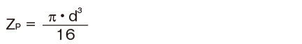
[Reference] Section Modulus (Solid Circle)
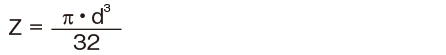
| Z | Section Modulus (mm3) |
|---|---|
| d | Shaft outer diameter (mm) |
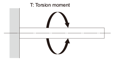
Spline Shaft Receiving a Torsion Load
When a torsion load is applied on the spline shaft of a Ball Spline, obtain the spline shaft diameter using the equation (2) below.

| T | Maximum torsion moment (N・mm) |
|---|---|
| τa | Permissible torsion stress of the spline shaft (49N/mm2) |
| Zp | Polar modulus of section of the spline nut (mm3) |
(see Table3 , Table4 , Table5 and Table6)
[Reference] Section Modulus (Solid Circle)
| ZP | Section modulus (mm3) |
|---|---|
| d | Shaft outer diameter (mm) |
When the Spline Shaft Simultaneously Receives a Bending Load and a Torsion Load
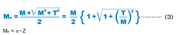
When the spline shaft of a Ball Spline receives a bending load and a torsion load simultaneously, calculate two separate spline shaft diameters: one for the equivalent bending moment (Me) and the other for the equivalent torsion moment (Te). Then, use the greater value as the spline shaft diameter.
Equivalent bending moment
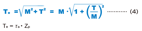
Equivalent torsion moment
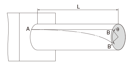
Rigidity of the Spline Shaft
The rigidity of the spline shaft is expressed as a torsion angle per meter of shaft length. Its valueshould be limited within 1°/4.
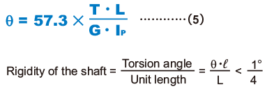
| θ | Torsion angle (°) |
|---|---|
| L | Spline shaft length (mm) |
| G | Transverse elastic modulus (7.9×10⁴N/mm2) |
| ℓ | Unit length (1000mm) |
| Ip | Polar moment of inertia (mm4) |
(see Table3 , Table4 , Table5 and Table6)
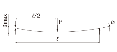
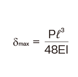
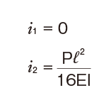
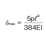
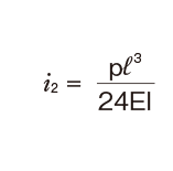
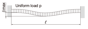
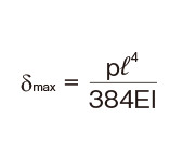
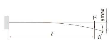
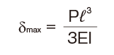
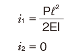
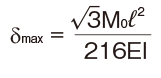
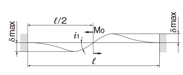
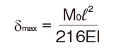
Deflection and Deflection Angle of the Spline Shaft
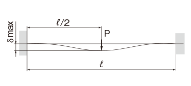
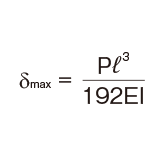
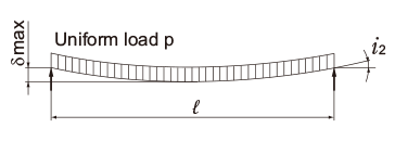
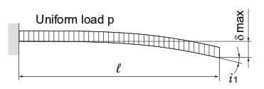
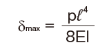
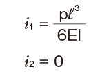
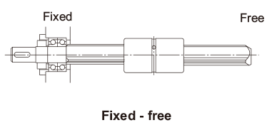
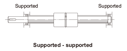
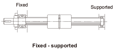
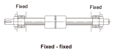
The deflection and deflection angle of the Ball Spline shaft need to be calculated using equations that meet the relevant conditions. Table1 and Table2 represent these conditions and the corresponding equations.
Table3, Table4, Table5 and Table6 show the section modulus of the spline shaft (Z) and the second moment of area (I). Using the Z and I values from the tables, the strength and displacement (deflection) of a typical ball spline within each model type can be obtained.
| Support method |
Condition | Deflection equation | Deflection angle equation |
|---|---|---|---|
| Both ends free |
 |
 |
 |
| Both ends fas- tened |
 |
 |
 |
| Both ends free |
 |
 |
 |
| Both ends fas- tened |
 |
 |
 |
| Support method |
Condition | Deflection equation | Deflection angle equation |
|---|---|---|---|
| One end fas- tened |
 |
 |
 |
| One end fas- tened |
 |
 |
 |
| Both ends free |
 |
 |
 |
| Both ends fas- tened |
 |
 |
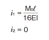 |
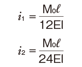
M0:Moment (N・mm)
l: Span (mm)
I: Geometrical moment of inertia (mm4)
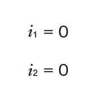
i1:Deflection angle at loading point
P: Concentrated load (N)
p: Uniform load (N/mm)
E: Modulus of longitudinal elasticity 2.06×10⁵(N/mm2)
Dangerous Speed of the Spline Shaft
When a Ball Spline shaft is used to transmit power while rotating, as the rotational speed of the shaft increases, the rotation cycle nears the natural frequency of the spline shaft. It may cause resonance and eventually result in inability to move. Therefore, the maximum rotational speed of the shaft must be limited to below the dangerous speed that does not cause resonance.
The dangerous speed of the spline shaft is obtained using the equation (6).
(0.8 is multiplied as a safety factor)
If the shaft’s rotation cycle exceeds or nears the resonance point during operation,it is necessaryto reconsider the spline shaft diameter.
Dangerous Speed
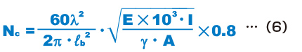
| Nc | Dangerous speed (min-1) |
|---|---|
| ℓb | Distance between two mounting surfaces (mm) |
| E | Young’s modulus (2.06×10⁵N/mm2) |
| I | Minimum geometrical moment of inertia of the shaft (mm4)
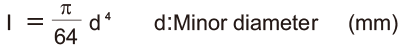 (see Table10 , Table11 , Table12 and Table13 on Sectional Shape of the Spline Shaft ) |
| γ | Density (specific gravity) (7.85×10⁻⁶kg/mm3)
 (see Table10 , Table11 , Table12 and Table13 on Sectional Shape of the Spline Shaft ) |
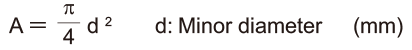
| A | Spline shaft cross-sectional area (mm2) |
| λ | Factor according to the mounting method
|
Cross-sectional Characteristics of the Spline Shaft
Cross-sectional Characteristics of the Spline Shaft for Ball Spline Models SLS, SLS-L and SLF
| Nominal shaft diameter | I: Geometrical moment of inertia mm4 |
Z: Modulus section mm3 |
IP: Polar moment of inertia mm4 |
ZP: Section modulus mm3 |
|
|---|---|---|---|---|---|
| 25 | Solid shaft | 1.61×10⁴ | 1.29×10³ | 3.22×10⁴ | 2.57×10³ |
| Hollow shaft Type K | 1.51×10⁴ | 1.20×10³ | 3.01×10⁴ | 2.41×10³ | |
| 30 | Solid shaft | 3.33×10⁴ | 2.22×10³ | 6.65×10⁴ | 4.43×10³ |
| Hollow shaft Type K | 3.00×10⁴ | 2.00×10³ | 6.01×10⁴ | 4.00×10³ | |
| 40 | Solid shaft | 1.09×10⁵ | 5.47×10³ | 2.19×10⁵ | 1.09×10⁴ |
| Hollow shaft Type K | 9.79×10⁴ | 4.90×10³ | 1.96×10⁵ | 9.79×10³ | |
| 50 | Solid shaft | 2.71×10⁵ | 1.08×10⁴ | 5.41×10⁵ | 2.17×10⁴ |
| Hollow shaft Type K | 2.51×10⁵ | 1.01×10⁴ | 5.03×10⁵ | 2.01×10⁴ | |
| 60 | Solid shaft | 5.83×10⁵ | 1.94×10⁴ | 1.17×10⁶ | 3.89×10⁴ |
| Hollow shaft Type K | 5.32×10⁵ | 1.77×10⁴ | 1.06×10⁶ | 3.54×10⁴ | |
| 70 | Solid shaft | 1.06×10⁶ | 3.02×10⁴ | 2.11×10⁶ | 6.04×10⁴ |
| 80 | Solid shaft | 1.82×10⁶ | 4.55×10⁴ | 3.64×10⁶ | 9.10×10⁴ |
| Hollow shaft Type K | 1.45×10⁶ | 3.62×10⁴ | 2.90×10⁶ | 7.24×10⁴ | |
| 100 | Solid shaft | 4.50×10⁶ | 9.00×10⁴ | 9.00×10⁶ | 1.80×10⁵ |
| Hollow shaft Type K | 3.48×10⁶ | 6.96×10⁴ | 6.96×10⁶ | 1.36×10⁵ | |
Note) For the hole-shape of the hollow spline shaft, see Sectional Shape of the Spline Shaft.
Cross-sectional Characteristics of the Spline Shaft for Ball Spline Models LBS, LBST,LBF, LBR, LBH, LBG and LBGT
| Nominal shaft diameter | I: Geometrical moment of inertia mm4 |
Z: Modulus section mm3 |
IP: Polar moment of inertia mm4 |
ZP: Section modulus mm3 |
|
|---|---|---|---|---|---|
| 15 | Solid shaft | 1.27×10³ | 2.00×10² | 2.55×10³ | 4.03×10² |
| 20 | Solid shaft | 3.82×10³ | 4.58×10² | 7.72×10³ | 9.26×10² |
| Hollow shaft Type K | 3.79×10³ | 4.56×10² | 7.59×10³ | 9.11×10² | |
| 25 | Solid shaft | 9.62×10³ | 9.14×10² | 1.94×10⁴ | 1.85×10³ |
| Hollow shaft Type K | 9.50×10³ | 9.05×10² | 1.90×10⁴ | 1.81×10³ | |
| 30 | Solid shaft | 1.87×10⁴ | 1.50×10³ | 3.77×10⁴ | 3.04×10³ |
| Hollow shaft Type K | 1.78×10⁴ | 1.44×10³ | 3.57×10⁴ | 2.88×10³ | |
| 40 | Solid shaft | 6.17×10⁴ | 3.69×10³ | 1.25×10⁵ | 7.46×10³ |
| Hollow shaft Type K | 5.71×10⁴ | 3.42×10³ | 1.14×10⁵ | 6.84×10³ | |
| 50 | Solid shaft | 1.49×10⁵ | 7.15×10³ | 3.01×10⁵ | 1.45×10⁴ |
| Hollow shaft Type K | 1.34×10⁵ | 6.46×10³ | 2.69×10⁵ | 1.29×10⁴ | |
| 60 | Solid shaft | 3.17×10⁵ | 1.26×10⁴ | 6.33×10⁵ | 2.53×10⁴ |
| Hollow shaft Type K | 2.77×10⁵ | 1.11×10⁴ | 5.54×10⁵ | 2.21×10⁴ | |
| 70 | Solid shaft | 5.77×10⁵ | 1.97×10⁴ | 1.16×10⁶ | 3.99×10⁴ |
| Hollow shaft Type K | 5.07×10⁵ | 1.74×10⁴ | 1.01×10⁶ | 3.49×10⁴ | |
| 85 | Solid shaft | 1.33×10⁶ | 3.69×10⁴ | 2.62×10⁶ | 7.32×10⁴ |
| Hollow shaft Type K | 1.11×10⁶ | 3.10×10⁴ | 2.22×10⁶ | 6.20×10⁴ | |
| 100 | Solid shaft | 2.69×10⁶ | 6.25×10⁴ | 5.33×10⁶ | 1.25×10⁵ |
| Hollow shaft Type K | 2.18×10⁶ | 5.10×10⁴ | 4.37×10⁶ | 1.02×10⁵ | |
| 120 | Solid shaft | 5.95×10⁶ | 1.13×10⁵ | 1.18×10⁷ | 2.26×10⁵ |
| Hollow shaft Type K | 5.28×10⁶ | 1.01×10⁵ | 1.06×10⁷ | 2.02×10⁵ | |
| 150 | Solid shaft | 1.61×10⁷ | 2.40×10⁵ | 3.20×10⁷ | 4.76×10⁵ |
| Hollow shaft Type K | 1.40×10⁷ | 2.08×10⁵ | 2.79×10⁷ | 4.16×10⁵ | |
Note) For the hole-shape of the hollow spline shaft, see Sectional Shape of the Spline Shaft.
Cross-sectional Characteristics of the Spline Shaft for Ball Spline Models LT, LF, LTR and LTR-A
| Nominal shaft diameter | I: Geometrical moment of inertia mm4 |
Z: Modulus section mm3 |
IP: Polar moment of inertia mm4 |
ZP: Section modulus mm3 |
||
|---|---|---|---|---|---|---|
| 4 | Solid shaft | 11.39 | 5.84 | 22.78 | 11.68 | |
| 5 | Solid shaft | 27.88 | 11.43 | 55.76 | 22.85 | |
| 6 | Solid shaft | 57.80 | 19.7 | 1.19×10² | 40.50 | |
| Hollow shaft Type K | 55.87 | 18.9 | 1.16×10² | 39.20 | ||
| 8 | Solid shaft | 1.86×10² | 47.4 | 3.81×10² | 96.60 | |
| Hollow shaft Type K | 1.81×10² | 46.0 | 3.74×10² | 94.60 | ||
| 10 | Solid shaft | 4.54×10² | 92.6 | 9.32×10² | 1.89×10² | |
| Hollow shaft Type K | 4.41×10² | 89.5 | 9.09×10² | 1.84×10² | ||
| 13 | Solid shaft | 1.32×10³ | 2.09×10² | 2.70×10³ | 4.19×10² | |
| Hollow shaft Type K | 1.29×10³ | 2.00×10² | 2.63×10³ | 4.09×10² | ||
| 16 | Solid shaft | 3.09×10³ | 3.90×10² | 6.18×10³ | 7.80×10² | |
| Hollow shaft | Type K | 2.97×10³ | 3.75×10² | 5.95×10³ | 7.51×10² | |
| Type N | 2.37×10³ | 2.99×10² | 4.74×10³ | 5.99×10² | ||
| 20 | Solid shaft | 7.61×10³ | 7.67×10² | 1.52×10⁴ | 1.53×10³ | |
| Hollow shaft | Type K | 7.12×10³ | 7.18×10² | 1.42×10⁴ | 1.43×10³ | |
| Type N | 5.72×10³ | 5.77×10² | 1.14×10⁴ | 1.15×10³ | ||
| 25 | Solid shaft | 1.86×10⁴ | 1.50×10³ | 3.71×10⁴ | 2.99×10³ | |
| Hollow shaft | Type K | 1.75×10⁴ | 1.41×10³ | 3.51×10⁴ | 2.83×10³ | |
| Type N | 1.34×10⁴ | 1.08×10³ | 2.68×10⁴ | 2.16×10³ | ||
| 30 | Solid shaft | 3.86×10⁴ | 2.59×10³ | 7.71×10⁴ | 5.18×10³ | |
| Hollow shaft | Type K | 3.53×10⁴ | 2.37×10³ | 7.07×10⁴ | 4.74×10³ | |
| Type N | 2.90×10⁴ | 1.95×10³ | 5.80×10⁴ | 3.89×10³ | ||
| 32 | Solid shaft | 5.01×10⁴ | 3.15×10³ | 9.90×10⁴ | 6.27×10³ | |
| Hollow shaft | Type K | 4.50×10⁴ | 2.83×10³ | 8.87×10⁴ | 5.61×10³ | |
| Type N | 3.64×10⁴ | 2.29×10³ | 7.15×10⁴ | 4.53×10³ | ||
| 40 | Solid shaft | 1.22×10⁵ | 6.14×10³ | 2.40×10⁵ | 1.21×10⁴ | |
| Hollow shaft | Type K | 1.10×10⁵ | 5.55×10³ | 2.17×10⁵ | 1.10×10⁴ | |
| Type N | 8.70×10⁴ | 4.39×10³ | 1.71×10⁵ | 8.64×10³ | ||
| 50 | Solid shaft | 2.97×10⁵ | 1.20×10⁴ | 5.94×10⁵ | 2.40×10⁴ | |
| Hollow shaft | Type K | 2.78×10⁵ | 1.12×10⁴ | 5.56×10⁵ | 2.24×10⁴ | |
| Type N | 2.14×10⁵ | 8.63×10³ | 4.29×10⁵ | 1.73×10⁴ | ||
| 60 | Solid shaft | 6.16×10⁵ | 2.07×10⁴ | 1.23×10⁶ | 4.14×10⁴ | |
| Hollow shaft Type K | 5.56×10⁵ | 1.90×10⁴ | 1.13×10⁶ | 3.79×10⁴ | ||
| 80 | Solid shaft | 1.95×10⁶ | 4.91×10⁴ | 3.90×10⁶ | 9.82×10⁴ | |
| Hollow shaft Type K | 1.58×10⁶ | 3.97×10⁴ | 3.15×10⁶ | 7.95×10⁴ | ||
| 100 | Solid shaft | 4.78×10⁶ | 9.62×10⁴ | 9.56×10⁶ | 1.92×10⁵ | |
| Hollow shaft Type K | 3.76×10⁶ | 7.57×10⁴ | 7.52×10⁶ | 1.51×10⁵ | ||
Note) For the hole-shape of the hollow spline shaft.
For type K: see Sectional Shape of the Spline Shaft.
For type N: see Sectional Shape of the Spline Shaft.
Cross-sectional Characteristics of the Spline Shaft for Ball Spline Models LT-X, LF-X, LFK-X, and LFH-X
| Nominal shaft diameter | I: Geometrical moment of inertia mm4 |
Z: Modulus section mm3 |
IP: Polar moment of inertia mm4 |
ZP: Section modulus mm3 |
||
|---|---|---|---|---|---|---|
| 3 | Solid shaft | 3.6 | 2.4 | 7.3 | 5 | |
| 4 | Solid shaft | 11.2 | 5.7 | 23.2 | 11.8 | |
| 5 | Solid shaft | 27.7 | 11.3 | 57.2 | 23.3 | |
| 6 | Solid shaft | 57.7 | 19.6 | 119.1 | 40.4 | |
| Hollow shaft | Type K | 55.8 | 18.9 | 115.3 | 39.1 | |
| 8 | Solid shaft | 175.6 | 45 | 366.2 | 93.9 | |
| Hollow shaft | Type K | 171.6 | 44 | 358.2 | 91.8 | |
| 10 | Solid shaft | 422.3 | 86.5 | 896.9 | 183.8 | |
| Hollow shaft | Type K | 409.7 | 84 | 871.7 | 178.6 | |
| 13 | Solid shaft | 1215.3 | 191.3 | 2574.6 | 405.3 | |
| Hollow shaft | Type K | 1184.6 | 186.5 | 2513.2 | 395.6 | |
| 16 | Solid shaft | 2734.3 | 350.8 | 5844.5 | 749.7 | |
| Hollow shaft | Type K | 2616.4 | 335.6 | 5608.8 | 719.5 | |
| Type N | 2015.6 | 258.6 | 4407.2 | 565.4 | ||
| 20 | Solid shaft | 7043.9 | 716.5 | 14731.7 | 1498.5 | |
| Hollow shaft | Type K | 6553 | 666.6 | 13749.9 | 1398.7 | |
| Type N | 5158.1 | 524.7 | 10960.2 | 1114.9 | ||
| 25 | Solid shaft | 17268.2 | 1404.2 | 36067.4 | 2932.9 | |
| Hollow shaft | Type K | 16250.3 | 1321.4 | 34031.6 | 2767.4 | |
| Type N | 12115.2 | 985.2 | 25761.4 | 2094.8 | ||
| 30 | Solid shaft | 36115.8 | 2444.1 | 75160 | 5086.3 | |
| Hollow shaft | Type K | 32898.8 | 2226.4 | 68726.1 | 4650.9 | |
| Type N | 26569.7 | 1798 | 56067.4 | 3794.2 | ||