Nominal Life
A ball spline in motion under an external load receives repeated stress on its raceways and rolling elements. When the stress reaches the limit, the surface of the raceways and rolling elements flake in places due to rolling fatigue. The service life of the ball spline is the total travel distance until the first flaking occurs on any of the raceways or the rolling elements as a result of rolling fatigue of the material. The nominal life defined below is used as an estimate for the service life of a ball spline. Nominal life is the total travel distance that 90% of a group of identical ball splines independently operating under the same conditions can achieve without flaking.
Calculating the Nominal Life
The nominal life of a Ball Spline varies with types of loads applied during operation: torque load, radial load and moment load. The corresponding nominal life values are obtained using the equations (11) to (15) below. (The basic load ratings in these loading directions are indicated in the specification table for the corresponding model number.)
Calculating the Nominal Life
The nominal life of the THK ball spline is defined as 50 km. The nominal life (L10) is calculated from the basic dynamic load rating (C) and the load acting on the ball spline (PC) using the following formulas.
-
When a Torque Load is Applied

-
When a Radial Load is Applied

| L10 | Nominal life (km) |
|---|---|
| CT | Basic dynamic torque rating (N・m) |
| C | Basic dynamic load rating (N) |
| TC | Calculated torque applied (N・m) |
| PC | Calculated radial load (N) |
* These nominal life formulas may not apply if the length of the stroke is less than or equal to twice the length of the ball spline nut.
When comparing the nominal life (L10), you must take into account whether the basic dynamic load rating was defined based on 50 km or 100 km. Convert the basic dynamic load rating based on ISO 14728-1 as necessary.
ISO-regulated basic dynamic load rating conversion formula:

| C50 | Basic dynamic load rating based on a nominal life of 50 km |
|---|---|
| C100 | Basic dynamic load rating based on a nominal life of 100 km |
Calculating the Modified Nominal Life
During use, a ball spline may be subjected to vibrations and shocks as well as fl uctuating loads, which are diffi cult to detect. In addition, the operating temperature and having nuts arranged in close contact will signifi cantly impact the service life. Taking these factors into account, the modifi ed nominal life (L10m) can be calculated according to the following formulas (13) and (14).
Modified factor α
| α | Modified factor |
|---|---|
| fT | Temperature factor (see Fig.1 ) |
| fC | Contact factor (see Table 8 ) |
| fW | Load factor (see Table 9 ) |
Modified nominal life L10m
-
When a Torque Load is Applied

-
When a Radial Load is Applied

| L10m | Modified nominal life (km) |
|---|---|
| CT | Basic dynamic torque rating (N・m) |
| C | Basic dynamic load rating (N) |
| TC | Calculated torque applied (N・m) |
| PC | Calculated radial load (N) |
Calculating the Service Life Time
When the nominal life (L10) has been obtained in the equation above, if the stroke length and the number of reciprocations per minute are constant, the service life time is obtained using the equation (15) below.
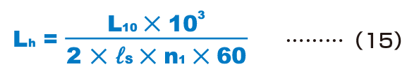
| Lh | Service life time (h) |
|---|---|
| ℓS | Stroke length (m) |
| n1 | Number of reciprocations per minute (min-1) |
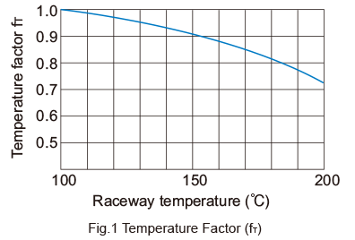
fT: Temperature factor
If the temperature of the environment surrounding the operating Ball Spline exceeds 100°C, take into account the adverse effect of the high temperature and multiply the basic load ratings by the temperature factor indicated in Fig.1 .
In addition, the Ball Spline must be of a high temperature type.
- Note) If the environment temperature exceeds 80°C, hightem-perature types of seal and retainer are required.Contact THK for details.
fC : Contact Factor
When multiple spline nuts are used in close contact with each other, their linear motion is affected by moments and mounting accuracy, making it difficult to achieve uniform load distribution. In such applications, multiply the basic load rating (C) and (C0) by the corresponding contact factor in Table8 .
- Note) If uneven load distribution is expected in a large machine, take into account the respective contact factor indicated in Table8 .
| Number of spline nuts in close contact with each other |
Contact factor fc |
|---|---|
| 2 | 0.81 |
| 3 | 0.72 |
| 4 | 0.66 |
| 5 | 0.61 |
| Normal use | 1 |
fW : Load Factor
In general, reciprocating machines tend to experience vibrations or impacts during operation, and it is difficult to accurately determine the vibrations generated during high-speed operation and impacts during frequent starts and stops. When the actual load applied to a ball spline cannot be obtained, or when speed and vibrations have a significant influence, divide the basic dynamic load rating (C) by the corresponding load factor in Table 9 , which has been empirically obtained.
| Vibrations/ impact |
Speed (V) | fw |
|---|---|---|
| Faint | Very low V≦0.25m/s |
1 to 1.2 |
| Weak | Slow 0.25<V≦1m/s |
1.2 to 1.5 |
| Medium | Medium 1<V≦2m/s |
1.5 to 2 |
| Strong | High V>2m/s |
2 to 3.5 |
Calculating the Average Load
When the load applied on the spline shaft fluctuates according to varying conditions, such as an industrial robot arm traveling forward while holding a workpiece and traveling backward with empty weight, and a machine tool handling various workpieces, this varying load condition must be taken into account in service life calculation.
The average load (Pm) is a constant load under which the service life of an operating Ball Spline with its spline nut receiving a fluctuation load in varying conditions is equivalent to the service life underthis varying load condition.
The following is the basic equation.
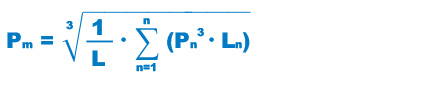
| Pm | Average Load (N) |
|---|---|
| Pn | Varying load (N) |
| L | Total travel distance (mm) |
| Ln | Distance traveled under Pn (mm) |
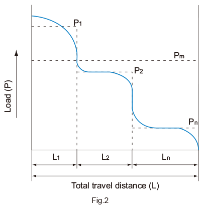
When the Load Fluctuates Stepwise
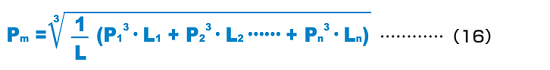
| Pm | Average Load (N) |
|---|---|
| Pn | Varying load (N) |
| L | Total travel distance (m) |
| Ln | Distance traveled under load Pn (m) |
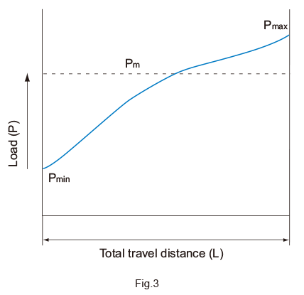
When the Load Fluctuates Monotonically

| Pmin | Minimum load (N) |
|---|---|
| Pmax | Maximum load (N) |
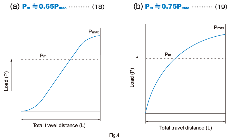
When the Load Fluctuates Sinusoidally
Equivalent Factor
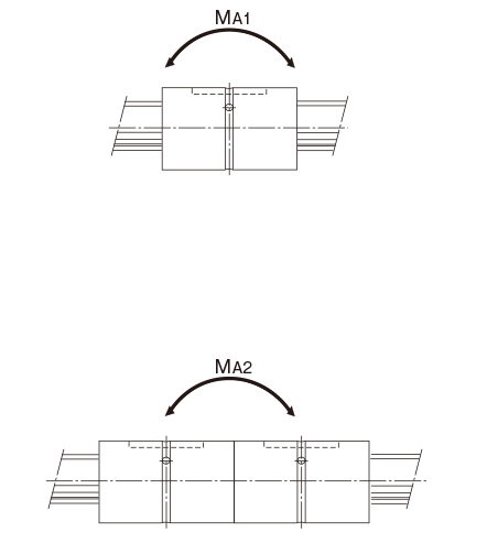
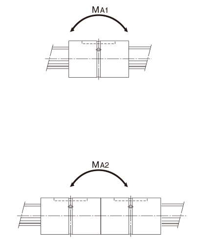
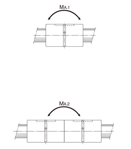
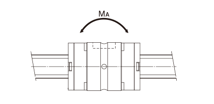
Table14, Table15, Table16 and Table17 show equivalentradial load factors calculated under a moment load.
Table of Equivalent Factors for Ball Spline Models SLS/SLF
| Model No. | Equivalent factor: K | |
|---|---|---|
| Single spline nut | Two spline nuts in close contact with each other |
|
| SLS/SLF 25 SLS 25L |
0.187 | 0.030 |
| 0.148 | 0.027 | |
| SLS/SLF 30 SLS 30L |
0.153 | 0.027 |
| 0.129 | 0.024 | |
| SLS/SLF 40 SLS 40L |
0.114 | 0.021 |
| 0.102 | 0.019 | |
| SLS/SLF 50 SLS 50L |
0.109 | 0.018 |
| 0.091 | 0.017 | |
| SLS/SLF 60 SLS 60L |
0.080 | 0.015 |
| 0.072 | 0.014 | |
Table of Equivalent Factors for Ball Spline Model LBS
| Model No. | Equivalent factor: K | |
|---|---|---|
| Single spline nut | Two spline nuts in close contact with each other |
|
| LBS 15 | 0.22 | 0.039 |
| LBS20 LBST 20 |
0.24 | 0.03 |
| 0.17 | 0.027 | |
| LBS25 LBST 25 |
0.19 | 0.026 |
| 0.14 | 0.023 | |
| LBS 30 LBST 30 |
0.16 | 0.022 |
| 0.12 | 0.02 | |
| LBS 40 LBST 40 |
0.12 | 0.017 |
| 0.1 | 0.016 | |
| LBS 50 LBST 50 |
0.11 | 0.015 |
| 0.09 | 0.014 | |
| LBST 60 | 0.08 | 0.013 |
| LBS 70 LBST 70 |
0.1 | 0.013 |
| 0.08 | 0.012 | |
| LBS 85 LBST 85 |
0.08 | 0.011 |
| 0.07 | 0.01 | |
| LBS 100 LBST 100 |
0.08 | 0.009 |
| 0.06 | 0.009 | |
| LBST 120 | 0.05 | 0.008 |
| LBST 150 | 0.045 | 0.006 |
- Note1) Values of equivalent factor K for model LBF are thesame as that for model LBS.
- Note2) Values of equivalent factor K for models LBR, LBG, LBGT and LBH are the same as that for modelLBST.
However the values of model LBF60 are the same as that for model LBST60.
The values of model LBH15 are the same as that for model LBS15.
Table of Equivalent Factors for Ball Spline Model LT
| Model No. | Equivalent factor: K | |
|---|---|---|
| Single spline nut | Two spline nuts in close contact with each other |
|
| LT 4 | 0.65 | 0.096 |
| LT 5 | 0.55 | 0.076 |
| LT 6 | 0.47 | 0.06 |
| LT 8 | 0.47 | 0.058 |
| LT 10 | 0.31 | 0.045 |
| LT 13 | 0.3 | 0.042 |
| LT 16 | 0.19 | 0.032 |
| LT 20 | 0.16 | 0.026 |
| LT 25 | 0.13 | 0.023 |
| LT 30 | 0.12 | 0.02 |
| LT 40 | 0.088 | 0.016 |
| LT 50 | 0.071 | 0.013 |
| LT 60 | 0.07 | 0.011 |
| LT 80 | 0.062 | 0.009 |
| LT 100 | 0.057 | 0.008 |
- Note) Values of equivalent factor K for models LF, LTR and LTR-A are the same as that for model LT.
However, the equivalent factor for model LTR32 is the same as that for model LT30.
Table of Equivalent Factors for Ball Spline Model LT-X
| Model No. | Equivalent factor: K | |
|---|---|---|
| Single spline nut | Two spline nuts in close contact with each other |
|
| LT/LF3X,3XD | 1.108 | - |
| LT/LF4X | 0.995 | 0.135 |
| LT/LF5X | 0.980 | 0.125 |
| LT/LF5XL | 0.430 | 0.0740 |
| LT/LF6X | 0.660 | 0.0993 |
| LT?lf6XL | 0.360 | 0.0633 |
| LT/LF8X | 0.420 | 0.0626 |
| LT/LF8XL | 0.210 | 0.0409 |
| LT/LF10X | 0.251 | 0.0470 |
| LT/LF13X | 0.241 | 0.0420 |
| LT/LF16X | 0.173 | 0.0320 |
| LT/LF20X | 0.129 | 0.0250 |
| LT/LF25X | 0.114 | 0.0220 |
| LT/LF30X | 0.101 | 0.0200 |
- Note) The values shown are those for models equipped with seals.
Values of equivalent factor K for model LF-X are the same as that for model LT-X.