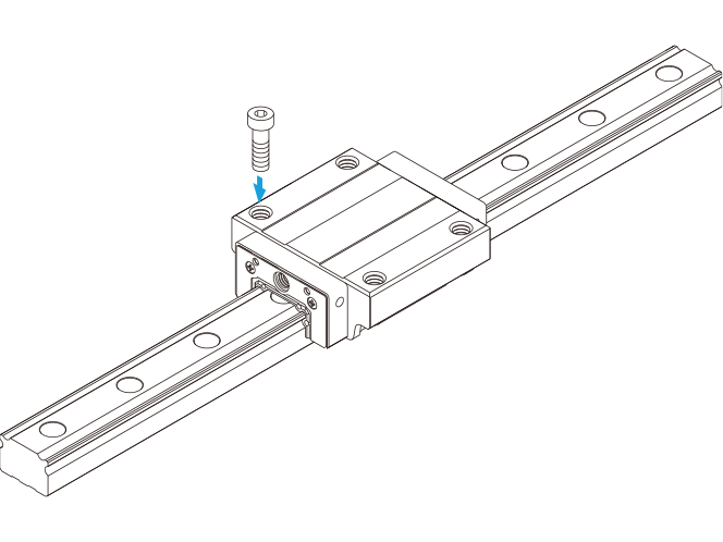
Full-Ball LM Guide Super-Heavy Load (Radial) Models NRS-X / NRS for Machine Tools Model NRS-A
The flange of its LM block has tapped holes.
Basic load rating (kN): Basic dynamic load rating 212 to 376 / Basic static load rating 431 to 737
Size :
75,85,100

Select display items
Click on the feature tag you wish to view and press the button to display. Detailed information is displayed at the bottom of the screen.
- Select all
- Deselect all
Detailed information
-
 Easy product comparisonsHighlight feature
 -
 Save items for laterreview Favorites feature
THK Online Services
Member-Exclusive Content
These contents can be accessed
after registering as a member.
Benefit 1: Useful features
Benefit 2: Exclusive content
| Products | Contents |
|---|---|
| LM Guide | LM rail standard lengths and maximum length, tapped-hole type LM rail, frame for LM rail clamps, steel plate for LM rail clamps, etc. |
| Ball Screw | Axial clearance, maximum manufacturing length of shaft, etc. |
| Actuator | Movable part mass, etc. |
Optional
Contamination Protection
Block Compatible Option
Seal and Metal Scraper
- End seal
- Side seal
- Inner seal
- With end seal + side seal + inner seal
- With double seals + side seal + inner seal
- With end seal + side seal + inner seal + metal scraper
- With double seals + side seal + inner seal + metal scraper
- The LM Block Dimension with Seals Attached
- Maximum Seal Resistance
- Laminated Contact Scraper LaCS
- The LM Block Dimension with LaCS is Attached
- Incremental Dimension with Grease Nipple when LaCS is Attached
- Maximum Resistance for Laminated Contact Scraper LaCS
- Side Scraper
- Maximum resistance for the side scraper
- Protector
- The LM Block Dimension with Protector is Attached
- Light-Resistance Contact Seal LiCS
- The LM Block Dimension with LiCS is Attached
- Incremental Dimension with Grease Nipple When LiCS is Attached
- Maximum Resistance for Light-Resistance Contact Seal LiCS
- High Chemical Resistance Fluorine Seal FS
- Overall block length with fluorine seals and other accessories attached
- Maximum Seal Resistance of High Chemical Resistance Fluorine Seal FS
Rail Compatible Option
Cover
- Plate Cover SV
- Plate Cover
- Steel Tape SP
- Dedicated Bellows
- Dedicated LM Cover
Cap
- Dedicated Cap for LM Rail Mounting Holes Cap CV/Cap C
- Dedicated Cap for LM Rail Mounting Holes Cap GC
Lubrication
Block Compatible Option
Lubrication
- QZ Lubricator
- LM Block Dimension (L Dimension) with QZ Lubricator Attached
Rustprevention
Block and Rail Compatible Option
Surface Treatment
- Surface Treatment
Material
- Stainless Steel Products
Other
Maintenance
- Lubrication Adapter
- Removing/mounting Jig
- End Piece EP
Display result
- Detailed information
- Optional
Detailed information
Dimensional drawing/Dimensional table
THK Online Services
Member-Exclusive Content
These contents can be accessed
after registering as a member.
Benefit 1: Useful features
-
 Easy product comparisonsHighlight feature
 -
 Save items for laterreview Favorites feature
Benefit 2: Exclusive content
| Products | Contents |
|---|---|
| LM Guide | LM rail standard lengths and maximum length, tapped-hole type LM rail, frame for LM rail clamps, steel plate for LM rail clamps, etc. |
| Ball Screw | Axial clearance, maximum manufacturing length of shaft, etc. |
| Actuator | Movable part mass, etc. |
Optional
No option tag has been selected.
Check detailed information with the tool
Click on the icon for the item you want to see in detail. Member registration and login are required for use.
Designer is the former optimal product selection tool
You can download 2D/3D CAD by clicking on the icon and selecting from the CAD format.