Installation Procedure
When using clearance adjustment bolts:
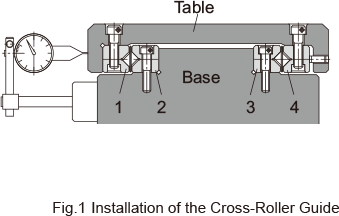
- Closely contact rails 2 and 3 onto the base, and rail 1 onto the table, and then firmly tighten the rail mounting bolts.
- Temporarily fasten rail 4 to the table.
Note) The rail mounting bolts must be designed so that they can be fully fastened while maintaining the rail installed.
- Place the base and the tables as shown in Fig.1 , and then insert the roller cage from the end. If the cage does not enter because there is no clearance, slide rail 4 toward the adjustment bolt first, and then insert the cage again.
- Place a dial gauge as shown in Fig.1 . Then, lightly screw all adjustment bolts evenly until the clearance is almost eliminated while gently pressing the table sideways.
- Attach the stopper to the rail end.
- Slide the table and adjust the cage position so as to achieve the required stroke.
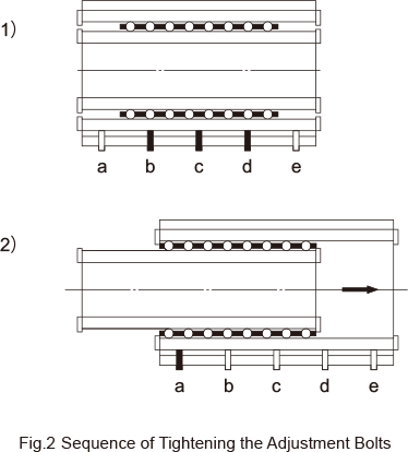
- Position the roller cage in the center of the rail as shown in Fig.2-1. Then, evenly tighten the adjustment bolts (b, c and d) that are within the area where the roller is present until the dial gauge indicates the required displacement. Fully fasten the mounting bolts where adjustment was performed.
Note) The displacement indicated on the gauge represents the preload per roller cage.
- Slide the table as shown in Fig. 2-2, and adjust the remaining adjustment bolts (a and e) in the same manner.
Note) When installing two or more units, first measure the tightening torque of the adjustment bolts for the first unit or the sliding resistance of the fist unit. Then, install the second (and later) unit so that its/their tightening torque(s) or sliding resistance(s) equal(s) that of the first unit. In this way, almost uniform preloads can be provided.