Assembling the Linear Bushing
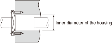
Inner Diameter of the Housing
Table1shows recommended housing inner-diameter tolerance for the Linear Bushing. When fitting the Linear Bushing with the housing, loose fit is normally recommended. If the clearance needs tobe smaller, provide transition fit.
| Type | Housing | ||
|---|---|---|---|
| Model No. | Accuracy | Loose fit | Transition fit |
| LM and LM-N | High accuracy grade (no symbol) |
H7 | J7 |
| Precision Grade (P) |
H6 | J6 | |
| LME and LME-N | — | H7 | K6, J6 |
| LMF | High accuracy grade (no symbol) |
H7 | J7 |
| LMK | |||
| LMH | |||
| LM-L and LM-NL | |||
| LMF-L | |||
| LMK-L | |||
| LMH-L | |||
| LMIF | |||
| LMIK | |||
| LMIH | |||
| LMIF-L | |||
| LMIK-L | |||
| LMIH-L | |||
| LMCF-L | |||
| LMCK-L | |||
| LMCH-L | |||
Clearance between the Nut and the LM Shaft
When using the Linear Bushing in combination with an LM shaft, use normal clearance in ordinary use and small gap if the clearance is to be minimized.
Note1) If the clearance after installation is to be negative, it is preferable not to exceed the radial clearance tolerance indicated in the specification table.
Note2) The shaft tolerance for Linear Bushing models SC, SL SH and SH-L falls under high accuracy grade (no symbol).
| Type | LM Shaft | ||
|---|---|---|---|
| Model No. | Accuracy | Normal clearance | Small gap |
| LM and LM-N | High accuracy grade (no symbol) |
f6, g6 | h6 |
| Precision Grade (P) |
f5, g5 | h5 | |
| LME and LME-N | — | h7 | k6 |
| LMF | High accuracy grade (no symbol) |
f6, g6 | h6 |
| LMK | |||
| LMH | |||
| LM-L and LM-NL | |||
| LMF-L | |||
| LMK-L | |||
| LMH-L | |||
| LMIF | |||
| LMIK | |||
| LMIH | |||
| LMIF-L | |||
| LMIK-L | |||
| LMIH-L | |||
| LMCF-L | |||
| LMCK-L | |||
| LMCH-L | |||
Mounting the Nut
Although the Linear Bushing does not require a large amount of strength for securing it in the axial direction, do not rely only on a press fit to support the nut. For the housing inner-diameter tolerance, see Table1.
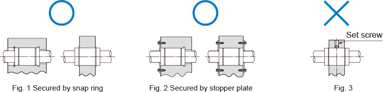
Mounting a Standard Linear Bushing
Example mountings are shown in Fig. 1 and Fig. 2 . Use snap rings or stopper plates to secure linear bushings.Securing the nut by pressing against the outer surface with one set screw as shown in Fig. 3willcause the nut to be deformed.
Snap Ring for Installation
The snap ring types shown in Table 3 can be used for securing the standard Model LM.
Note 1) For models indicated with parentheses, use Cshape concentric snap rings.
Note 2) Table 3 commonly applies to models LM, LM-GA, LM-MG and LM-L.
| Snap ring | ||||
|---|---|---|---|---|
| Model No. | For outer surface | For inner surface | ||
| Needle snap |
C-shape snap |
Needle snap |
C-shape snap |
|
| LM 3 | — | — | AR 7 | — |
| LM 4 | — | — | 8 | — |
| LM 5 | WR 10 | 10 | 10 | 10 |
| LM 6 | 12 | 12 | 12 | 12 |
| LM 8 | — | 15 | 15 | 15 |
| LM 8S | — | 15 | 15 | 15 |
| LM 10 | 19 | 19 | 19 | 19 |
| LM 12 | 21 | 21 | 21 | 21 |
| LM 13 | 23 | 22 | 23 | — |
| LM 16 | 28 | — | 28 | 28 |
| LM 20 | 32 | — | 32 | 32 |
| LM 25 | 40 | 40 | 40 | 40 |
| LM 30 | 45 | 45 | 45 | 45 |
| LM 35 | 52 | 52 | 52 | 52 |
| LM 38 | — | 56・58 | 57 | — |
| LM 40 | — | 60 | 60 | 60 |
| LM 50 | — | 80 | 80 | 80 |
| LM 60 | — | 90 | 90 | 90 |
| LM 80A | — | 120 | 120 | 120 |
| LM 100A | — | (150) | 150 | — |
| LM 120A | — | (180) | 180 | — |
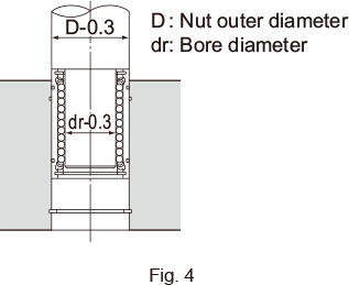
Inserting the Nut
When inserting the standard linear bushing into a housing, do not directly hit the seal or side plate. Use a jig to evenly drive in the nut, or place a flatter piece of metal on the nut and gently hit that. (See Fig. 4 )
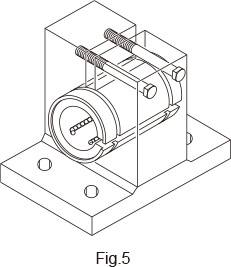
Installing a Clearance-adjustable Type
To adjust the clearance of a clearance-adjustable type (-AJ), use a housing that allows adjustment of the nut outer diameter so as to facilitate the adjustment of the clearance between the Linear Bushing and the LM shaft. Positioning the slit of the Linear Bushing at an angle of 90° with the housing’s slit will provide uniform deformation in the circumferential direction. (See Fig.5 .)
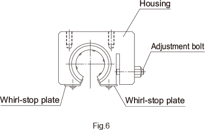
Mounting an Open Type
For an open type (-OP), also use a housing that allows adjustment of the nut outer diameter as shown in Fig.6 . Open types are normally used with a light preload. Be sure not to give an excessive preload.
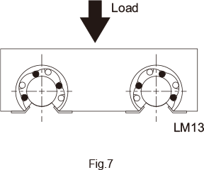
Precautions on Installing an Open Three-ball-row Type Linear Bushing
When installing an open three-ball-row type Linear Bushing, mount it while taking into account the load distribution as indicated in Fig.7.
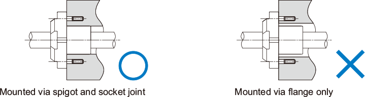
Installing the Flanged Type
With models LMF, LMK, LMH, LMIF, LMCF, LMIK, LMCK, LMIH, and LMCH, the nut is integrated with a flange. Therefore, the linear bushing can be mounted only via the flange.
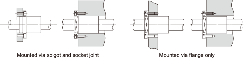
However, the Model LMJK must be mounted via a spigot and socket joint. Please do not mount using just the flange.
Installing the LM Case Unit
Attaching Model SC (SL)
Models SC and SL can be affixed from either above or below using bolts. (See Fig. 8 )
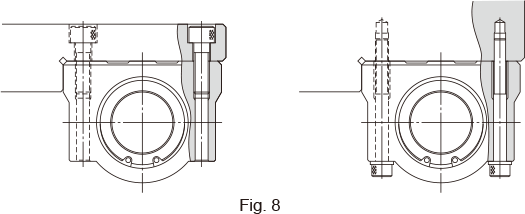
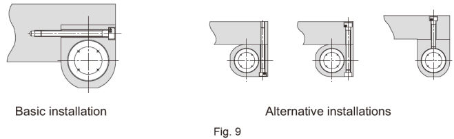
Attaching the Model SH (SH-L)
Models SH and SH-L can be affixed in any direction using bolts. (See Fig. 9 )
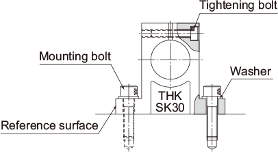
Mounting the Shaft End Support
Shaft end support model SK can easily be secured to the table using mounting bolts. Model SK enables the LM shaft to firmly be secured using tightening bolts.
Inserting the LM Shaft
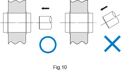
When inserting the LM shaft into the Linear Bushing, align the center of the shaft with that of the nut and gently insert the shaft straightforward into the nut. If the shaft is slanted while it is inserted, balls may fall off or the retainer may be deformed. (See Fig.10.)
When Under a Moment Load
When using the Linear Bushing, make sure the load is evenly distributed on the whole ball raceway.In particular, if a moment load is applied, use two or more Linear Bushing units on the same LM shaft and secure an adequately large distance between the units.
If using the Linear Bushing under a moment load, also calculate the equivalent radial load and identify the correct model number. (SeeRated Load and Nominal Life)
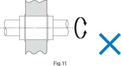
Rotational Use Not Allowed
The Linear Bushing is not suitable for rotational use for a structural reason. (See Fig.11 .) Forcibly rotating it may cause an unexpected accident.