Rated Load and Nominal Life
The rated load of the Linear Bushing varies according to the position of balls in relation to the load direction. The basic load ratings indicated in the specification tables each indicate the value when one row of balls receiving a load are directly under the load.
If the Linear Bushing is mounted so that two rows of balls evenly receive the load in the load direction, the rated load changes as shown in Table1 .
| Rows of balls | Ball position | Load Rating |
|---|---|---|
| 3 rows |
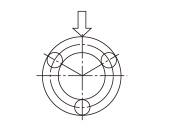 |
1×C |
| 4 rows |
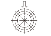 |
1.41×C |
| 5 rows |
 |
1.46×C |
| 6 rows |
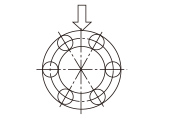 |
1.28×C |
| 8 rows |
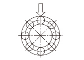 |
1.25×C |
For specific values for "C" above, see the respective specification table.
Calculating the Nominal Life
The nominal life of the THK linear bushing is defined as 50 km. The nominal life (L10) is calculated from the basic dynamic load rating (C) and the load acting on the linear bushing (PC) using the following formula.
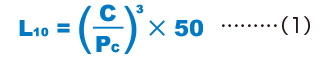
| L10 | Nominal life (km) |
|---|---|
| C | Basic dynamic load rating (N) |
| PC | Calculated load (N) |
* This nominal life formula may not apply if the length of the stroke is less than or equal to twice the length of the nut.
When comparing the nominal life (L10), you must take into account whether the basic dynamic load rating was defined based on 50 km or 100 km. Convert the basic dynamic load rating based on ISO 14728-1 as necessary.
ISO-regulated basic dynamic load rating conversion formula:

| C50 | Basic dynamic load rating based on a nominal life of 50 km |
|---|---|
| C100 | Basic dynamic load rating based on a nominal life of 100 km |
Calculating the Modifi ed Nominal Life
During use, a linear bushing may be subjected to vibrations and shocks as well as fluctuating loads, which are difficult to detect. In addition, the surface hardness of the raceways, the operating temperature, and having blocks arranged directly behind one another will have a decisive impact on the service life. Taking these factors into account, the modified nominal life (L10m) can be calculated according to the following formula (2).
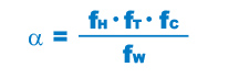
Modified factor α
Modified nominal life L10m
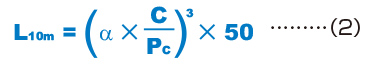
| L10m | Modified nominal life (km) |
|---|---|
| C | Basic dynamic load rating (N) |
| PC | Calculated load (N) |
When a Moment Load is Applied to a Single Nut or Two Nuts in Close Contact with Each Other
When a moment load is applied to a single nut or two nuts in close contact with each other, calculate the equivalent radial load at the time the moment is applied.

When a Moment Load and a Radial Load are Simultaneously Applied
When a moment and a radial load are applied simultaneously, calculate the service life based on the sum of the radial load and the equivalent radial load.
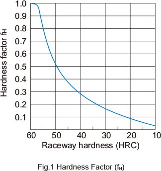
fH: Hardness Factor
To maximize the load capacity of the Linear Bushing, the hardness of the raceways needs to be between 58 to 64 HRC. If the hardness is lower than this range, the basic dynamic load rating and the basic static load rating decrease. Therefore, it is necessary to multiply each rating by the respective hardness factor (fH). Normally, fH = 1.0 since the Linear Bushing has sufficient hardness.
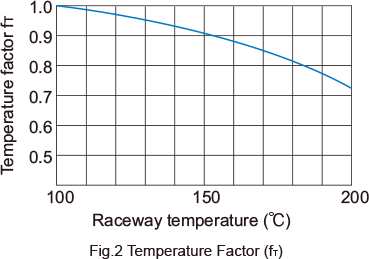
fT:Temperature Factor
If the temperature of the environment surrounding the operating Linear Bushing exceeds 100°C, take into account the adverse effect of the high temperature and multiply the basic load ratings by the temperature factor indicated in Fig.2 . Also note that the Linear Bushing itself must be of high temperature type.
Note) If the environment temperature exceeds 80°C, use a Linear Bushing type equipped with metal retainer plates.
fc : Contact Factor
When multiple nuts are used in close contact with each other, their linear motion is affected by moments and mounting accuracy, making it difficult to achieve uniform load distribution. In such applications, multiply the basic load rating (C) and (C0) by the corresponding contact factor in Table2 .
Note) If uneven load distribution is expected in a large machine, take into account the respective contact factor indicated in Table2 .
| Number of nuts in close contact with each other |
Contact factor fc |
|---|---|
| 2 | 0.81 |
| 3 | 0.72 |
| 4 | 0.66 |
| 5 | 0.61 |
| Normal use | 1 |
Note) If uneven load distribution is expected in a large machine, take into account the respective contact factor indicated in Table2 .
fw : Load Factor
In general, reciprocating machines tend to experience vibrations or impacts during operation, and it is extremely difficult to accurately determine the vibrations generated during highspeed operation and impacts during frequent starts and stops. Therefore, when the actual load applied to a linear bushing cannot be obtained, or when speed and impacts have a significant influence, divide the basic dynamic load rating (C) by the corresponding load factor in Table 3 , which has been empirically obtained.
| Vibrations/ impact |
Speed(V) | fw |
|---|---|---|
| Faint | Very low V≦0.25m/s |
1 to 1.2 |
| Weak | Slow 0.25<V≦1m/s |
1.2 to 1.5 |
| Medium | Medium 1<V≦2m/s |
1.5 to 2 |
| Strong | High V>2m/s |
2 to 3.5 |
Calculating the Service Life Time
When the nominal life (L10) has been obtained, if the stroke length and the number of reciprocations per minute are constant, the service life time is obtained using the following equation.
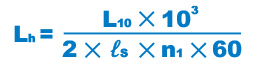
| Lh | Service life time (h) |
|---|---|
| ℓs | Stroke length (m) |
| n1 | Number of reciprocations per minute (min-1) |