Nominal Life
An LM Guide in motion under an external load receives repeated stress on its raceways and rolling elements. When the stress reaches the limit, the surface of the raceways and rolling elements fl ake in places due to rolling fatigue. This phenomenon is called fl aking. The service life of an LM Guide is the total travel distance until the fi rst fl aking occurs on any of the raceways or the rolling elements as a result of rolling fatigue of the material.
The nominal life defi ned below is typically used as a guideline for obtaining the service life of the LM Guide.
The nominal life means the total travel distance that 90% of a group of units of the same LM Guide model can achieve without fl aking after individually running under the same conditions.
Calculating the Nominal Life
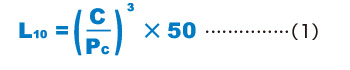
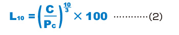
The nominal life (L10) of an LM Guide is obtained from the following formulas using the basic dynamic load rating (C), which is based on a reference distance of 50 km for an LM Guide with balls and 100 km for an LM Guide with rollers, and the calculated load acting on the LM Guide (PC).
LM Guide with balls (Using a basic dynamic load rating based on a nominal life of 50 km)
| L10 | Nominal life (km) |
|---|---|
| C | Basic dynamic load rating (N) |
| PC | Calculated load (N) |
LM Guide with rollers (Using a basic dynamic load rating based on a nominal life of 100 km)
Note: These nominal life formulas may not apply if the length of the stroke is less than or equal to twice the length of the LM block.
When comparing the nominal life (L10), you must take into account whether the basic dynamic load rating was defined based on 50 km or 100 km. Convert the basic dynamic load rating based on ISO 14728-1 as necessary.
ISO-regulated basic dynamic load rating conversion formulas:
- LM Guide with balls

C50 Basic dynamic load rating based on a nominal life of 50 km C100 Basic dynamic load rating based on a nominal life of 100 km - LM Guide with rollers

Calculating the Modified Nominal Life
During use, an LM Guide may be subjected to vibrations and shocks as well as fluctuating loads, which are difficult to detect. In addition, the surface hardness of the raceways, the operating temperature, and having LM blocks arranged directly behind one another will have a decisive impact on the service life. Taking these factors into account, the modified nominal life (L10m) can be calculated according to the following formulas (3) and (4).
Modified factor α
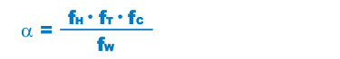
| α | Modified factor |
|---|---|
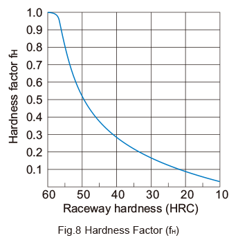
| fH | Hardness factor (see Fig.8Calculating the Modified Nominal Life) |
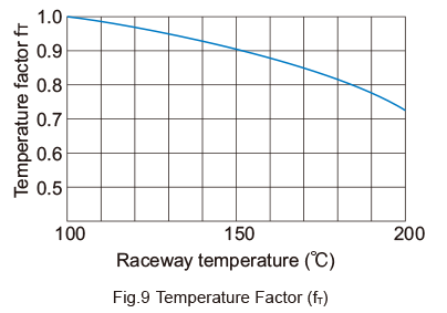
| fT | Temperature factor (see Fig.9Calculating the Modified Nominal Life) |
| fC | Contact factor (see Fig.10Calculating the Modified Nominal Life) |
| fW | Load factor (see Table11Calculating the Modifi ed Nominal Life) |
Modified nominal life L10m
- LM Guide with balls
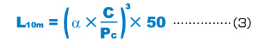
L10m Modified nominal life (km) C Basic dynamic load rating (N) PC Calculated load (N) - LM Guide with rollers

Once the nominal life (L10) has been obtained, the service life time can be obtained using the following equation if the stroke length and the number of reciprocations are constant.
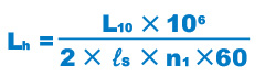
| Lh | Service life time (h) |
|---|---|
| ℓs | Stroke length (mm) |
| n1 | Number of reciprocations per minute(min-1) |
f H : Hardness factor
To ensure the achievement of the optimum load capacity of the LM Guide, the raceway hardness must be between 58 and 64 HRC. If the hardness is lower than this range, the basic dynamic load rating and the basic static load rating decrease. Therefore, it is necessary tomultiply each rating by the respective hardness factor (fH). Since the LM Guide has sufficient hardness, the fHvalue for the LM Guide is normally 1.0 unless otherwise specified.
fT :Temperature Factor
If the temperature of the environment surrounding the operating LM Guide exceeds 100°C, take into account the adverse effect of the hightemperature and multiply the basic load ratings by the temperature factor indicated in Fig.9 . In addition, the selected LM Guide must also be of a high temperature type.
Note) LM guides not designed to withstand high temperatures should be used at 80°C or less.Please contact THK if application requirements exceed 80°C.
fc: Contact Factor
When multiple LM blocks are used in close contact with each other, it is difficult to achieveuniform load distribution due to moment loads and mounting-surface accuracy. When using multiple blocks in close contact with each other, multiply the basic load rating (C0) by the corresponding contact factor indicated in Table10 .
Note) If uneven load distribution is expected in a large machine, take into account the respective contact factor indicated in Table10 .
| Number of blocks used in close contact |
Contact factor fc |
|---|---|
| 2 | 0.81 |
| 3 | 0.72 |
| 4 | 0.66 |
| 5 | 0.61 |
| 6 or more | 0.6 |
| Normal use | 1 |
fw: Load Factor
In general, reciprocating machines tend to involve vibrations or impact during operation. It is extremely difficult to accurately determine vibrations generated during high-speed operation and impact during frequent start and stop. Therefore, where the effects of speed and vibration are estimated to be significant, divide the basic dynamic load rating (C) by a load factor selected from Table11 , which contains empirically obtained data.
| Vibrations/ impact |
Speed (V) | fw |
|---|---|---|
| Faint | Very low V≦0.25m/s |
1 to 1.2 |
| Weak | low 0.25<V≦1m/s |
1.2 to 1.5 |
| Medium | Medium 1<V≦2m/s |
1.5 to 2 |
| Strong | High V>2m/s |
2 to 3.5 |
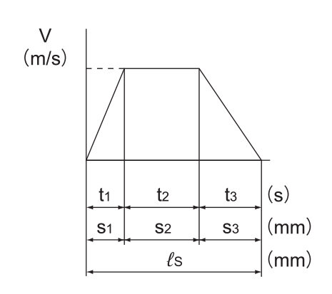
Example of Calculating the Nominal Life (1) - with Horizontal Mount and High-speed Acceleration
Conditions
- Model No.:
HSR35L
(basic dynamic load rating: C =65.0 kN)
(basic static load rating: C0 =91.7 kN) - Mass:
m1=800 kg
m2=500 kg - Speed:
V=0.5 m/s
- Time:
t1=0.05 s
t2=2.8 s
t3=0.15 s - Acceleration:
α1=10 m/s2
α3 =3.333 m/s2 - Stroke:
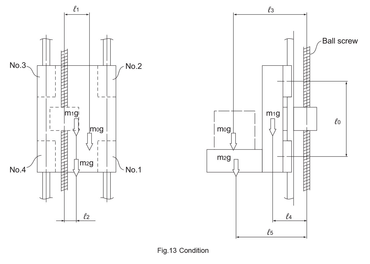
ℓS =1450 mm
- Distance:
ℓ0=600 mm
ℓ1=400 mm
ℓ2=120 mm
ℓ3=50 mm
ℓ4=200 mm
ℓ5=350 mm
Gravitational acceleration g=9.8(m/s2)
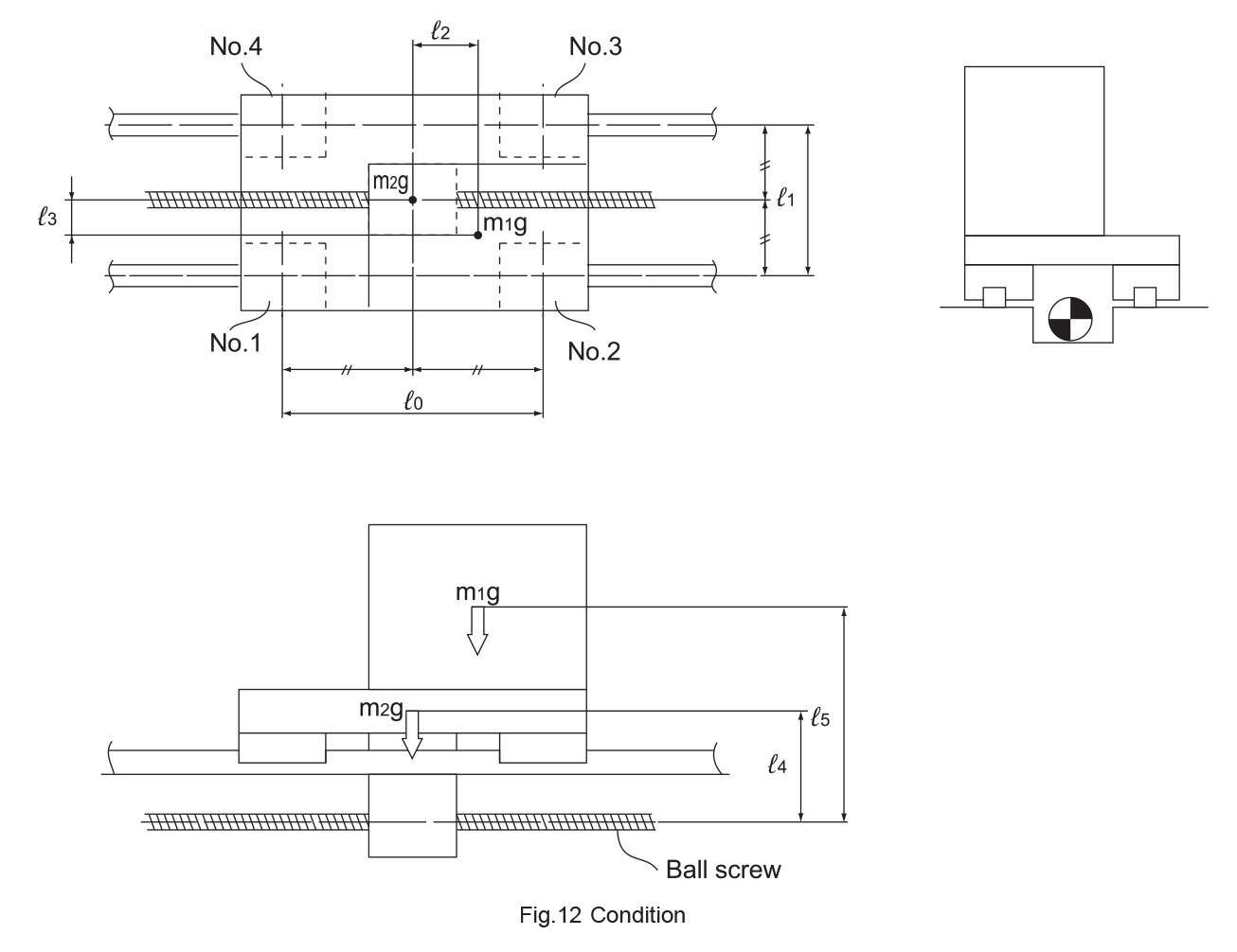
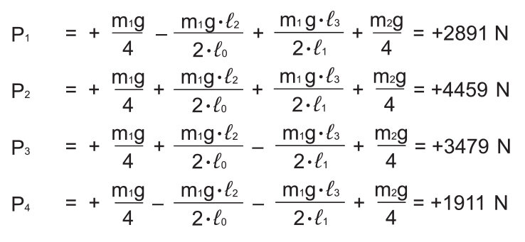
Load Applied to the LM Block
Calculate the load applied to each LM block.
●During uniform motion
■Applied load in the radial direction Pn
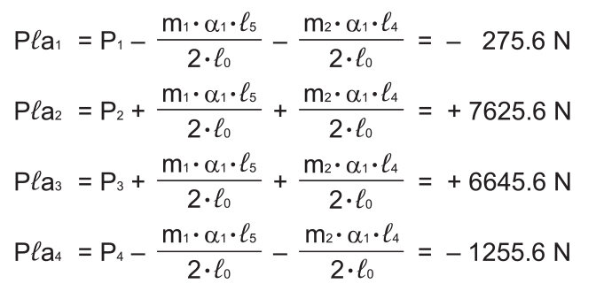
●During leftward acceleration
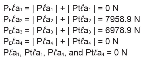
■Applied load in the radial direction Pℓan
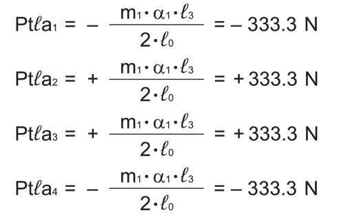
■Applied load in the lateral direction Ptℓan
●During leftward deceleration
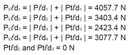
■Applied load in the radial direction Pℓdn
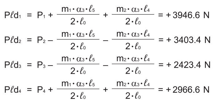
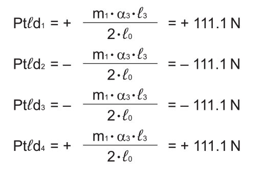
■Applied load in the lateral direction Ptℓdn
●During rightward acceleration
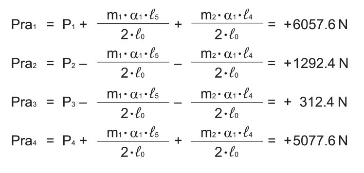
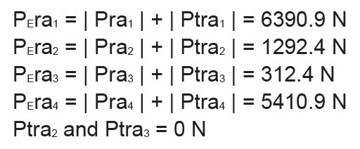
■Applied load in the radial direction Pran
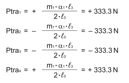
■Applied load in the lateral direction Ptran
●During rightward deceleration
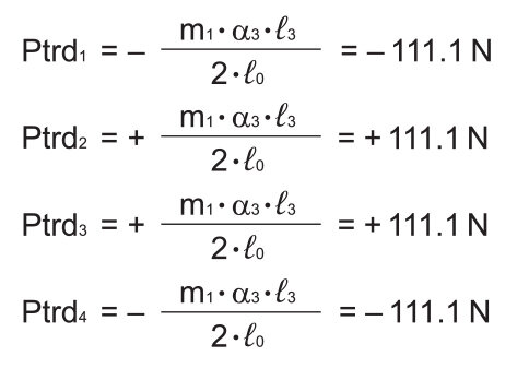
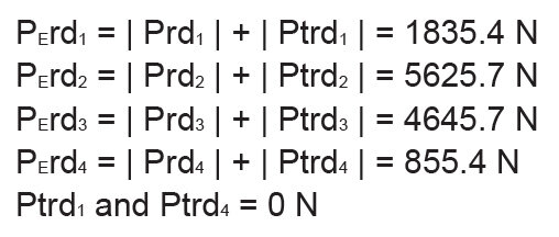
■Applied load in the radial direction Prdn
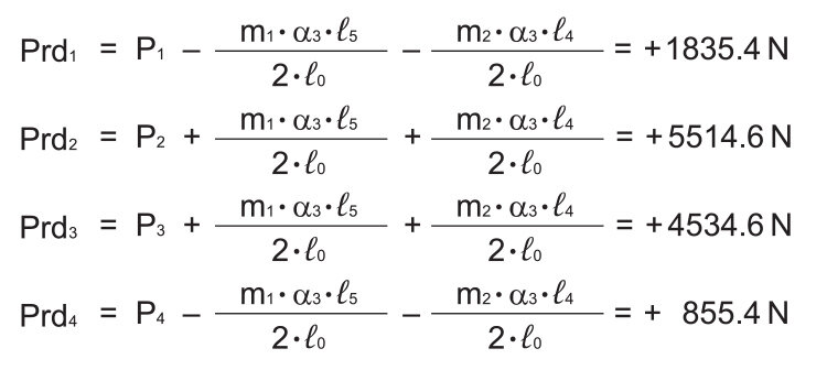
■Applied load in the lateral direction Ptrdn
Combined Radial And Thrust Load
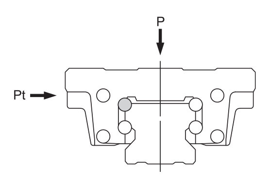
The combined radial and thrust load is calculated for each block only on the groove where the load is greatest.
Under these operating conditions, for each block, the groove for which the load is greatest is groove 1.※1 Because groove 1 bears P※2>0 and Pt>0 loads, it is 0 N when P<0 and Pt<0 loads are applied. When calculating for the groove that will bear P<0 and Pt<0 loads, use the absolute value of the load.
- ※1
The reason that groove 1 has the greatest load is that mass m1 is applied unevenly to the table and is not distributed equally to all grooves in the block.
- ※2
P refers to the radial load that each groove bears.
●During uniform motion
●During rightward acceleration
●During leftward acceleration
●During rightward deceleration
●During leftward deceleration
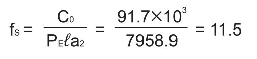
Static Safety Factor
As indicated above, the maximum load is applied to the LM Guide during the leftward acceleration of the second LM block. Therefore, the static safety factor (fS) is obtained in the following equation.
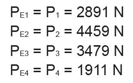
Average Load Pmn
Obtain the average load applied to each LM block.
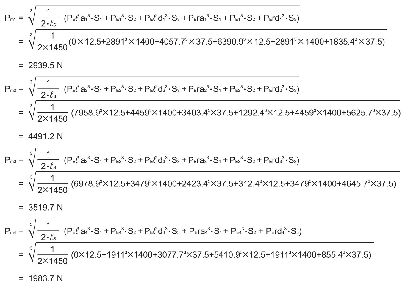
Nominal Life L10mn
The nominal life of the four LM blocks is obtained from the corresponding nominal life equations shown below.
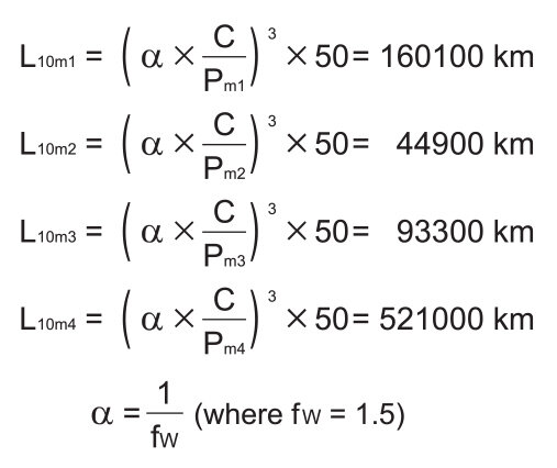
Therefore, the service life of the LM Guide used in a machine or equipment under the conditions stated above is equivalent to the nominal life of the second LM block, which is 44,900 km.
Example of Calculating the Nominal Life (2) - with Vertical Mount
Conditions
- Model No.:
HSR25CA2SS+1500L-Ⅱ
(basic dynamic load rating: C =27.6 kN)
(basic static load rating:C0 =36.4 kN) - Mass:
m0=100 kg
m1=200 kg
m2=100 kg - Stroke:
ℓS =1000 mm
- Distance:
ℓ0=300 mm
ℓ1=80 mm
ℓ2=50 mm
ℓ3=280 mm
ℓ4=150 mm
ℓ5=250 mm
The mass(m0)is loaded only during ascent; it is removed during descent.
Gravitational acceleration g=9.8(m/s2)
Load Applied to the LM Block
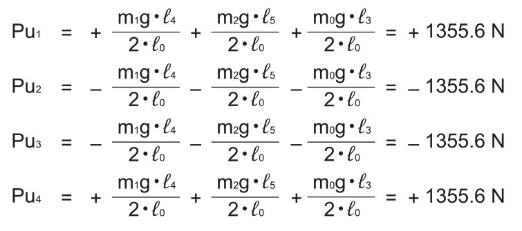
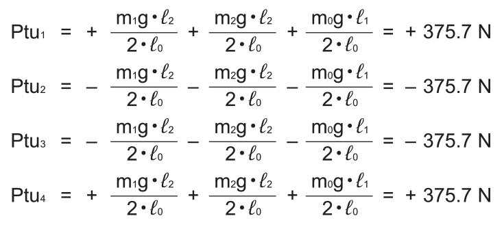
●During Ascent
■Load applied to each LM block in the radial direction Pun during ascent
■Load applied to each LM block in the lateral direction Ptun during ascent
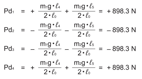
●During Descent
■Load applied to each LM block in the radial direction Pdn during descent
■Load applied to each LM block in the lateral direction Ptdn during descent
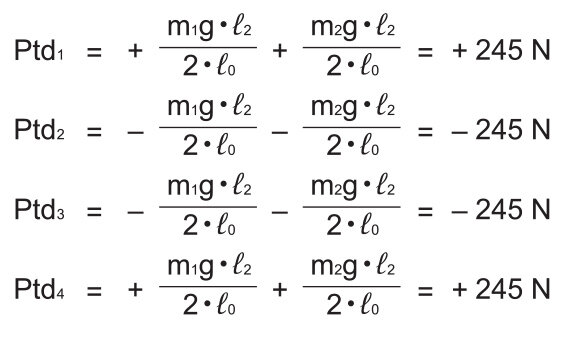
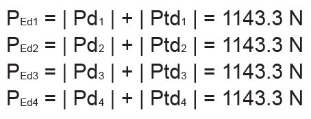
Combined Radial And Thrust Load
●During Ascent
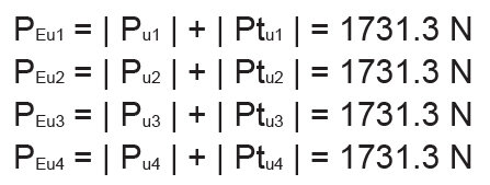
●During Descent
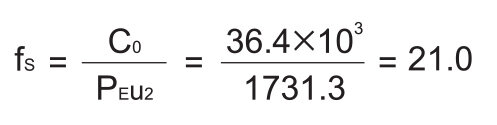
Static Safety Factor
The static safety factor(fS)of the LM Guide used in a machine or equipment under the conditions stated above is obtained as follows.
Average Load Pmn
Obtain the average load applied to each LM block.
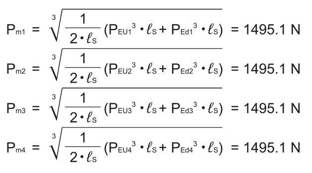
Nominal Life L10mn
The nominal life of the four LM blocks is obtained from the corresponding nominal life equations shown below.
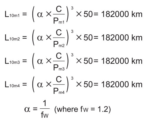
Therefore, the service life of the LM Guide used in a machine or equipment under the conditions stated above is 182,000 km.