Nominal Life
Static Safety Factor fS
The LM Roller may receive an unexpected external force while it is stationary or operative due to the generation of an inertia caused by vibrations and impact or start and stop. It is necessary to consider a static safety factor against such a working load.

| fS | Static safety factor |
|---|---|
| fC | Contact factor (see Table2 ) |
| C0 | Basic static load rating (kN) |
| PC | Calculated load (kN) |
Reference Value of Static Safety Factor
The static safety factors indicated in Table1 are the lower limits of reference values in the respective conditions.
| Machine using the LM system | Load conditions | Lower limit of fs |
|---|---|---|
| General industrial machinery | Without vibration or impact | 1 to 1.3 |
| With vibration or impact | 2 to 3 | |
| Machine tool | Without vibration or impact | 1 to 1.5 |
| With vibration or impact | 2.5 to 7 |
Calculating the Nominal Life
The nominal life of the THK LM roller is defined as 100 km. The nominal life (L10) is calculated from the basic dynamic load rating (C) and the load acting on the LM roller (PC) using the following formula.

| L10 | Nominal life (km) |
|---|---|
| C | Basic dynamic load rating (N) |
| PC | Calculated radial load (N) |
When comparing the nominal life (L10), you must take into account whether the basic dynamic load rating was defined based on 50 km or 100 km. Convert the basic dynamic load rating based on ISO 14728-1 as necessary. ISO-regulated basic dynamic load rating conversion formula:

| C50 | Basic dynamic load rating based on a nominal life of 50 km |
|---|---|
| C100 | Basic dynamic load rating based on a nominal life of 100 km |
Calculating the Modified Nominal Life
During use, an LM roller may be subjected to vibrations and shocks as well as fluctuating loads, which are difficult to detect. In addition, the hardness of the raceways, the operating temperature, and having LM rollers arranged in close contact will have a decisive impact on the service life. Taking these factors into account, the modified nominal life (L10m) can be calculated according to the following formula (2).
Modified factor α
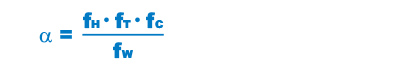
| α | Modified factor |
|---|---|
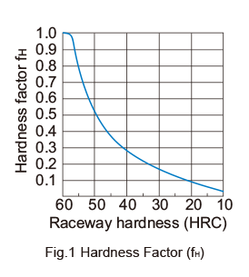
| fH | Hardness factor (see Fig.1) |
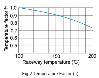
| fT | Temperature factor (see Fig.2) |
| fC | Contact factor (see Table2) |
| fW | Load factor (see Table 3) |
Modified nominal life L10m

| L10m | Modified nominal life (km) |
|---|---|
| C | Basic dynamic load rating (N) |
| P | Calculated radial load (N) |
Calculating the Service Life Time
When the nominal life (L10) has been obtained, if the stroke length and the number of reciprocations per minute are constant, the service life time is obtained using the following equation.

| Lh | Service life time (h) |
|---|---|
| ℓS | Stroke length (mm) |
| n1 | Number of reciprocations per minute (min-1) |
fH : Hardness Factor
To maximize the load capacity of the LM system, the hardness of the raceways needs to be between 58 to 64 HRC. If the hardness is lower than this range, the basic dynamic load rating and the basic static load rating decrease.Therefore, it is necessary to multiply each rating by the respective hardness factor (fH).
fT : Temperature Factor
If the temperature of the environment surrounding the operating LM Roller exceeds 100℃, take into account the adverse effect of the high temperature and multiply the basic load ratings by the temperature factor indicated in Fig.2 .
Note) The normal service temperature of the LM Roller is 80℃ at a maximum. If the ambient temperature exceeds 80℃, contact THK.
fC : Contact Factor
When multiple LM Roller units are used in near close contact with each other, their linear motion is affected by moments and mounting accuracy, making it difficult to achieve uniform load distribution. In such applications, multiply the basic load rating (C) and (C0) by the corresponding contact factor in Table2 .
Note) If uneven load distribution is expected in a large machine, take into account the respective contact factor indicated in Table2 .
| Number of LM Roller units in close contact with each other |
Contact factor fC |
|---|---|
| 2 | 0.81 |
| 3 | 0.72 |
| 4 | 0.66 |
| 5 | 0.61 |
| Normal use | 1 |
fW : Load Factor
In general, reciprocating machines tend to experience vibrations or impacts during operation, and it is extremely difficult to accurately determine the vibrations generated during highspeed operation and impacts during frequent starts and stops. Therefore, when the actual load applied to an LM roller cannot be obtained, or when speed and impacts have a significant influence, divide the basic dynamic load rating (C) by the corresponding load factor in Table 3 , which has been empirically obtained.
| Vibrations / impact | Speed(V) | fW |
|---|---|---|
| Faint | Very low V≦0.25m/s |
1 to 1.2 |
| Weak | Slow 0.25<V≦1m/s |
1.2 to 1.5 |
| Medium | Medium 1<V≦2m/s |
1.5 to 2 |
| Strong | High V>2m/s |
2 to 3.5 |