Load Rating and Nominal Life
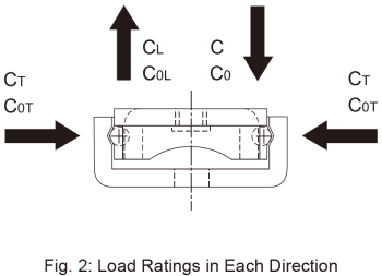
Load Ratings in Each Direction
The basic load rating in the specification table indicates the load rating in the radial direction as shown in Fig. 2. The load ratings in the reverse-radial and lateral directions are obtained from Table 1 below.
| Basic dynamic load rating | Basic static load rating | |
|---|---|---|
| Radial direction | C (indicated in the dimensional table) | C0 (indicated in the dimensional table) |
| Reverse-radial direction | CL=C | C0L=C0 |
| Lateral directions | CT=1.47C | C0T=1.73C0 |
Static Safety Factor fS
When the Model ER is stationary or in motion, an unexpected external force may be applied due to vibrations, impacts, or inertia caused by starting and stopping. It is necessary to take a safety factor into account with regard to this type of applied load.

| fS | Static safety factor (see Table 2 ) |
|---|---|
| fC | Contact factor (see Table 3 ) |
| C0 | Basic static load rating (N) |
| PC | Calculated load (N) |
Estimates of the Static Safety Factor
Treat the values in Table 2 as estimates for the lower limit of the static safety factor based on the operating conditions.
| Load conditions1 | Lower limit of fS |
|---|---|
| Without vibration or impacts | 1 to 1.3 |
| With vibration or impacts | 2 to 7 |
1 Vibrations and impacts are typically caused by factors such as acceleration and deceleration, sudden starting and stopping, vibrations and impacts from an external machine, and changes in processing power over time.
Calculating the Nominal Life
The nominal life of the THK precision linear pack is defined as 50 km. The nominal life (L10) is cal- culated from the basic dynamic load rating (C) and the load acting on the precision linear pack (PC) using the following formula.

| L10 | Nominal life (km) |
|---|---|
| C | Basic dynamic load rating (N) |
| PC | Calculated load (N) |
When comparing the nominal life (L10), you must take into account whether the basic dynamic load rating was defined based on 50 km or 100 km. Convert the basic dynamic load rating based on ISO 14728-1 as necessary.
ISO-regulated basic dynamic load rating conversion formulas:

| C50 | Basic dynamic load rating based on a nominal life of 50 km |
|---|---|
| C100 | Basic dynamic load rating based on a nominal life of 100 km |
Calculating the Modified Nominal Life
During use, a precision linear pack may be subjected to vibrations and shocks as well as fluctuating loads, which are difficult to detect. In addition, having precision linear packs arranged in close contact will have a decisive impact on the service life. Taking these factors into account, the modified nominal life (L10m ) can be calculated according to the following formula (2).
Modified factor α
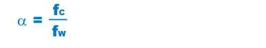
| α | Modified factor |
|---|---|
| fC | Contact factor (see Table 3) |
| fW | Load factor (see Table 4 ) |
Modified nominal life L10m

| L10m | Modified nominal life (km) |
|---|---|
| C | Basic dynamic load rating (N) |
| PC | Calculated load (N) |
Calculating the Service Life Time
Once the nominal life (L10) has been obtained, the service life time can be obtained using the following formula if the stroke length and the cycles per minute are constant.

| Lh | Service life time (h) |
|---|---|
| ℓS | Stroke length (mm) |
| n1 | Number of reciprocations per minute(min-1) |
fc: Contact Factor
When multiple inner blocks are used in close contact with each other, their linear motion is affected by a moment load and mounting accuracy, making it difficult to achieve uniform load distribution. In such applications, multiply the basic load rating (C) and (C0) by the corresponding contact factor in Table 3 .
| Number of inner blocks in close contact with each other |
Contact factor fC |
|---|---|
| 2 | 0.81 |
| 3 | 0.72 |
| Normal use 1 | 1 |
fW : Load Factor
In general, reciprocating machines tend to involve vibrations or impacts during operation. It is extremely difficult to accurately determine vibrations generated during high-speed operation and impacts that occur during frequent starts and stops. Therefore, when the actual load applied on Model ER cannot be obtained, or when speed and vibrations have a significant influence, divide the basic dynamic load rating (C) by the corresponding load factor in Table 4 of empirically obtained data.
| Vibrations/(br) impacts | Speed (V) | fW |
|---|---|---|
| Faint | Very low V≦0.25 m/s |
1 to 1.2 |
| Weak | Slow 0.25 m/sV≦1 m/s |
1.2 to 1.5 |