Installation
Slide Rail Mounting Screws
Since the space for securing the slide rail mounting screws is small, as shown in Fig. 1, we recommend using button head bolts or binding head bolts (JIS B 1111 annex).
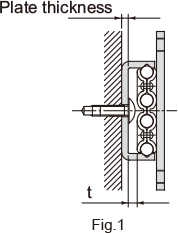
| Model No. | Mounting screw size | Rail plate thickness |
t |
|---|---|---|---|
| FBW 2560XR | M4 | 1.5 | 3.2 |
| FBW 3590XR | M4 | 2.5 | 3.4 |
| FBW 50110XR | M5 | 2.5 | 3.4 |
Attaching a Stopper
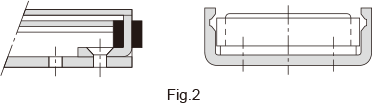
If the slider may overshoot and come off of the slide rail, attach a dedicated stopper to the slide rail end as shown in Fig. 2.
Installing the Slider
With Model FBW-XR, balls will not fall off even if the slider is removed from the slide rail. However, they could fall if the slider is twisted when reattaching it to the slide rail. Whenever possible, do not remove the slider from the slide rail when installing the slide pack.
Groove Dimensions
The groove dimensions when Model FBW-XR is installed in a groove are shown in Fig. 3.
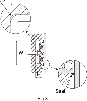
| Model No. | W | H | r (max) |
|---|---|---|---|
| FBW 2560XR |
24.8 +0.15 |
7.4 | 1 |
| FBW 3590XR |
37.4 +0.15 |
10 | 2 |
| FBW 50110XR |
50.4 +0.15 |
10 | 2.5 |
Note: The groove width for the FBW3590XR and 50110XR is 0.4 mm more than for the previous models (3590R and 50110R).