Mounting the Slide Rail
Mounting Screws of the Slide Rail
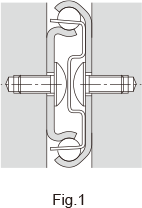
The slide rail is designed to be mounted using M4 screws. Since the mounting space is smallas shown in Fig.1 , we recommend using button head or binding head bolts.
Note that the mounting screw for the slide rail of the models indicated in the following table is different.
| Model number | button-head bolt |
binding-head bolt |
countersunk screw |
|---|---|---|---|
| Models FBL27S/27S-P14/27D | M3 | M3 , M4 | — |
| Model E15 | — | — | M2.6 |
| Models E20/D20 | — | — | M3 |
| Model FBL35E | M3 | M3 | — |
| Model E36RS | — | — | M4 |
Note) For button head bolts, binding head bolts, and countersunk screws, see the appendix of JIS B 1111.
Attaching the Slide Rail
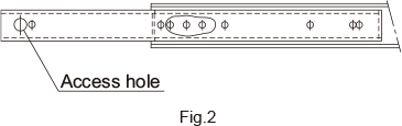
At full extension of the slide, mount the outer rail at the overlap of rails. Followed by full retraction of the slide and mount the opposite end using the access hole.
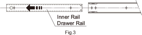
* For the following model numbers, mount outer rail after removing inner rail, as shown in Fig.3 .
Models: FBL27S-P14,FBL35S-P13,FBL35S-P14,FBL35M,FBL35J,FBL35B,FBL35E-P14,FBL35G-P13,FBL35G-P14,FBL51H-P13,FBL51H-P14,FBL56H-P13,FBL56H-P14 FBL35G-P13,FBL35G-P14,FBL51H-P13,FBL51H-P14,FBL56H-P13,FBL56H-P14
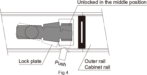
In addition, when mounting the outer rail or cabinet rail of models FBL35G-P13, FBL35G-P14, FBL51H-P13 and FBL56H-P13, which have locking mechanisms, release the lock by pressing the lock plate in the direction indicated in Fig.4 and adjust the position of the access hole.
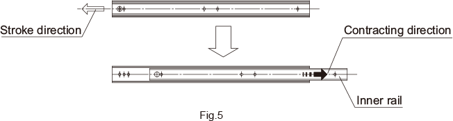
* For the following models, mount the inner rail by sliding it in the contracting direction as show in Fig.5 . When doing so, do not remove the inner rail from the outer rail. If the inner rail is pulled out, it may be difficult to reinsert.
Models: FBL27S, FBL35S
Permissible Load and Mounting Orientation
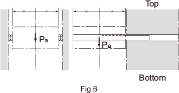
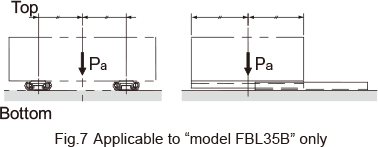
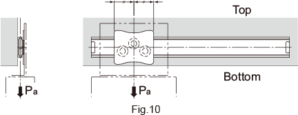
For use other than with the mounting orientation shown in Fig.6 , contact THK. The permissible load of the Slide Rail indicates the load in the direction Pa that two rails can receive in the middle of the inner rail length at the maximum stroke. The mounting orientation shown in Fig. 7is applicable to "model FBL35B" only.
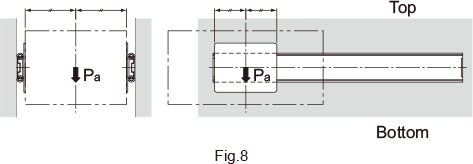
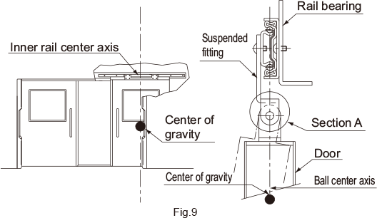
The mounting orientation of Fig.8 is applicable to model FBL35F. The mounting orientation of Fig.9must be used for model FBL48DR. To prevent a moment load from being applied, position the center of gravity of the door on the ball and cage center lines, and ensure that section A of the hanger is structured to allow free rotation. The mounting orientation of Fig.10 is applicable to model E36RS. Unlike other slide rails, model FBL48DR and model E36RS are used in a single rail configuration.Therefore, the load must be centered on the ball and the cage center line.
Surface Treatment
The surface of the Slide Rail is electro-galvanized (treated with trivalent chromate) as standard. The aluminum slide rail of models E and D is white alumite-treated as standard. The slider of model E36RS is electro-galvanized (trivalent chromate treatment) and the rail is white alumite-treated as standard. For other surface treatments, contact THK.