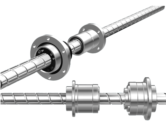
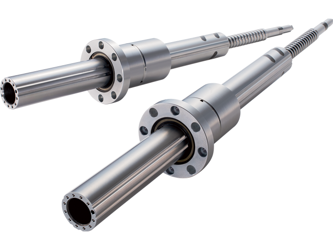
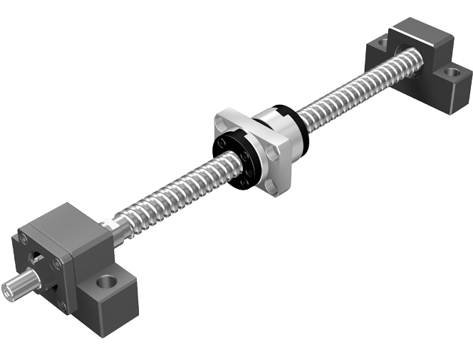
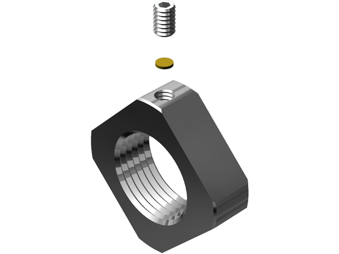
Ball Screw
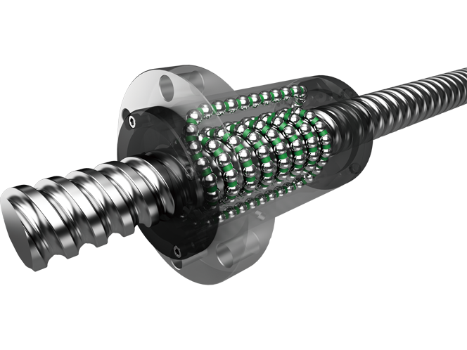
Ball screws are feed screws that provide high efficiency due to the rolling motion of the balls between the screw shaft and nut.
The drive torque is less than one-third that of a conventional sliding screw, making it ideal for power saving of the drive motor.
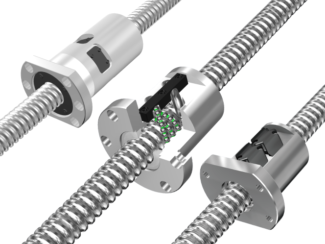
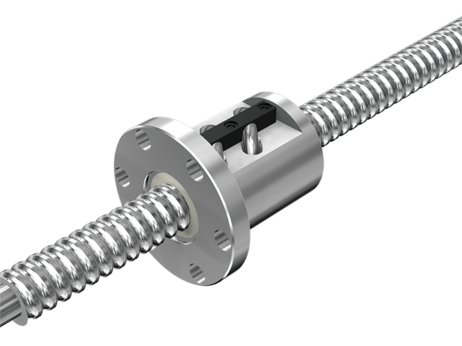
Types
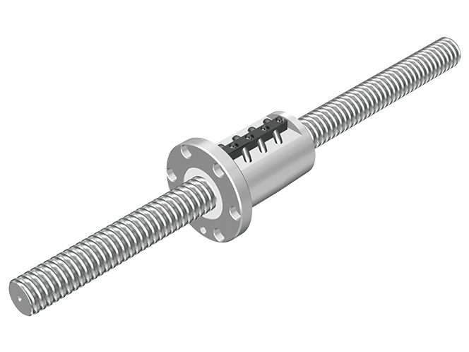
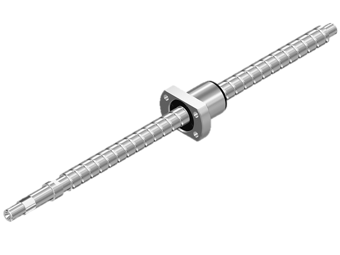
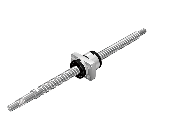
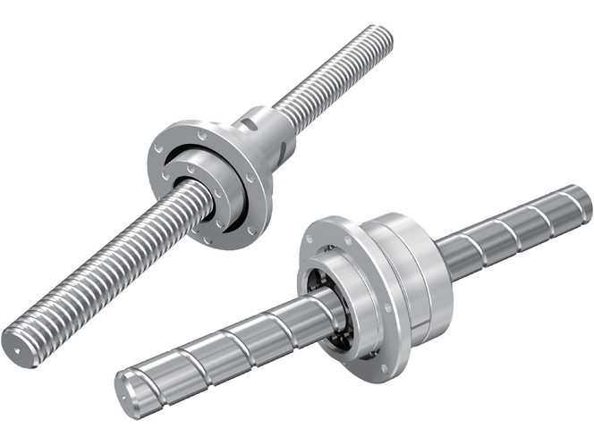
Features
Driving Torque One Third of the Sliding Screw
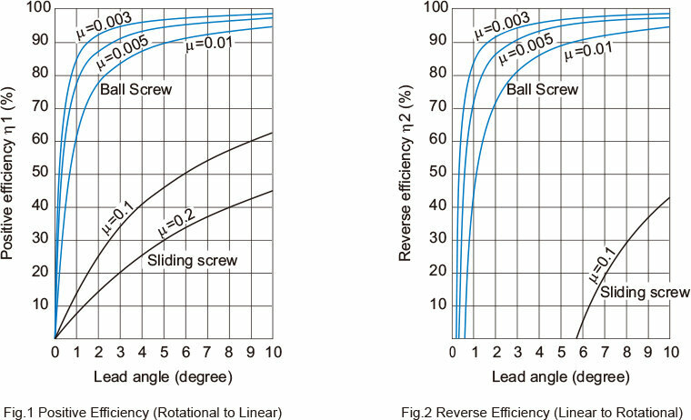
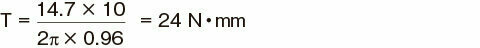
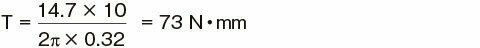
With the Ball Screw, balls roll between the screw shaft and the nut to achieve high efficiency. Its required driving torque is only one third of the conventional sliding screw. (See Fig.1 and Fig.2 .) As a result, it is capable of not only converting rotational motion to straight motion, but also converting straight motion to rotational motion.
Calculating the Lead Angle

| β | : Lead angle | (°) |
| dP | : Ball center-to-center diameter | (mm) |
| Ph | : Feed screw lead | (mm) |
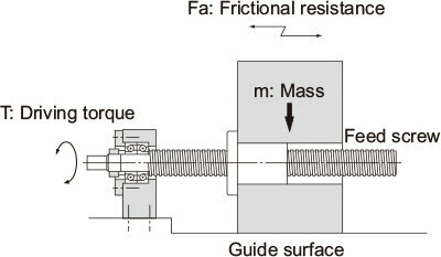
Relationship between Thrust and Torque
The torque or thrust generated when thrust or torque is applied is obtained from equations (1) to (3).
● Driving Torque Required to Gain Thrust

| T | : Driving torque | (N・mm) |
| Fa | : Frictional coefficient of the guide surface | (N) |
| Fa=μ×mg | ||
| μ | : Frictional coefficient of the guide surface | |
| g | : Gravitational acceleration | (9.8m/s2) |
| m | : Mass of the transferred object | (kg) |
| Ph | : Feed screw lead | (mm) |
| η1 | : Positive efficiency of feed screw | (Driving Torque One-Third That of the Sliding Screw see Fig.1) |
● Thrust Generated When Torque is Applied

| Fa | : Thrust generated | (N) |
| T | : Driving torque | (N・mm) |
| Ph | : Feed screw lead | (mm) |
| η1 | : Positive efficiency of feed screw | (Driving Torque One-Third That of the Sliding Screw see Fig.1) |
● Torque Generated When Thrust is Applied

| T | : Torque generated | (N・mm) |
| Fa | : Thrust generated | (N) |
| Ph | : Feed screw lead | (mm) |
| η2 | : Reverse efficiency of feed screw | (Driving Torque One-Third That of the Sliding Screw see Fig.2) |
Examples of Calculating Driving Torque
When moving an object with a mass of 500 kg using a screw with an effective diameter of 33 mm and a lead length of 10 mm (lead angle: 5°30'), the required torque is obtained as follows.
Rolling guide (= 0.003)
Ball Screw (from = 0.003, = 0.96)
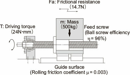
Frictional resistance on the guide surface
Fa=0.003×500×9.8=14.7N
Driving torque
Rolling guide (μ= 0.003)
Ball Screw (from μ= 0.2, η= 0.32)
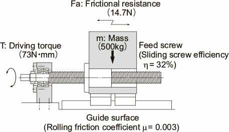
Frictional resistance on the guide surface
Fa=0.003×500×9.8=14.7N
Driving torque
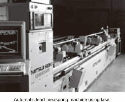
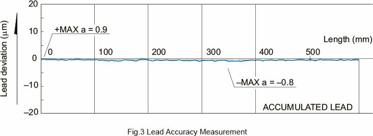
Ensuring High Accuracy
The Ball Screw is ground with the highest-level facilities and equipment at a strictly temperaturecontrolled factory, Its accuracy is assured under a thorough quality control system that covers assembly to inspection.
[Conditions]
Model No.: BIF3205-10RRG0+903LC2
|
Item |
Standard value |
Actual measurement |
|---|---|---|
|
Directional target point |
0 |
- |
|
Representative |
±0.011 |
-0.0012 |
|
Fluctuation |
0.008 |
0.0017 |
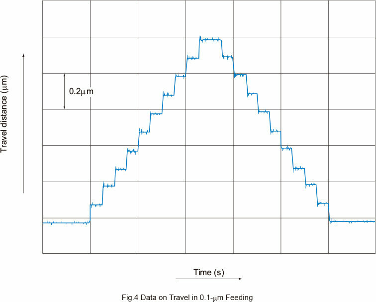
Capable of Micro Feeding
The Ball Screw requires a minimal starting torque due to its rolling motion, and does not cause a slip, which is inevitable with a sliding motion. Therefore, it is capable of an accurate micro feeding.Fig.4 shows a travel distance of the Ball Screw in one-pulse, 0.1-m feeding. (LM Guide is used for the guide surface.)
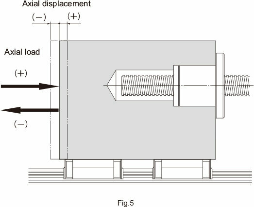
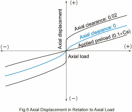
High Rigidity without Backlash
Since the Ball Screw is capable of receiving a preload, the axial clearance can be reduced to below zero and the high rigidity is achieved because of the preload. In Fig.5 , when an axial load is applied in the positive (+) direction, the table is displaced in the same (+) direction. When an axial load is provided in the reverse (-) direction, the table is displaced in the same (-) direction. Fig.6 shows the relationship between the axial load and the axial displacement. As indicated in Fig.6 , as the direction of the axial load changes, the axial clearance occurs as a displacement. Additionally, when the Ball Screw is provided with a preload, it gains a higher rigidity and a smaller axial displacement than a zero clearance in the axial direction.
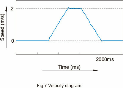
Capable of Fast Feed
Since the Ball Screw is highly efficient and generates little heat, it is capable of a fast feed.
Example of High Speed
Fig.7 shows a speed diagram for a large lead rolled Ball Screw operating at 2 m/s.
|
Item |
Description |
|---|---|
|
Sample |
Large Lead Rolled Ball Screw WTF3060 (Shaft diameter: 30mm; lead: 60mm) |
|
Maximum speed |
2m/s (Ball Screw rotational speed: 2,000 min-1) |
|
Guide surface |
LM Guide model SR25W |