

- Pick and Place
- System
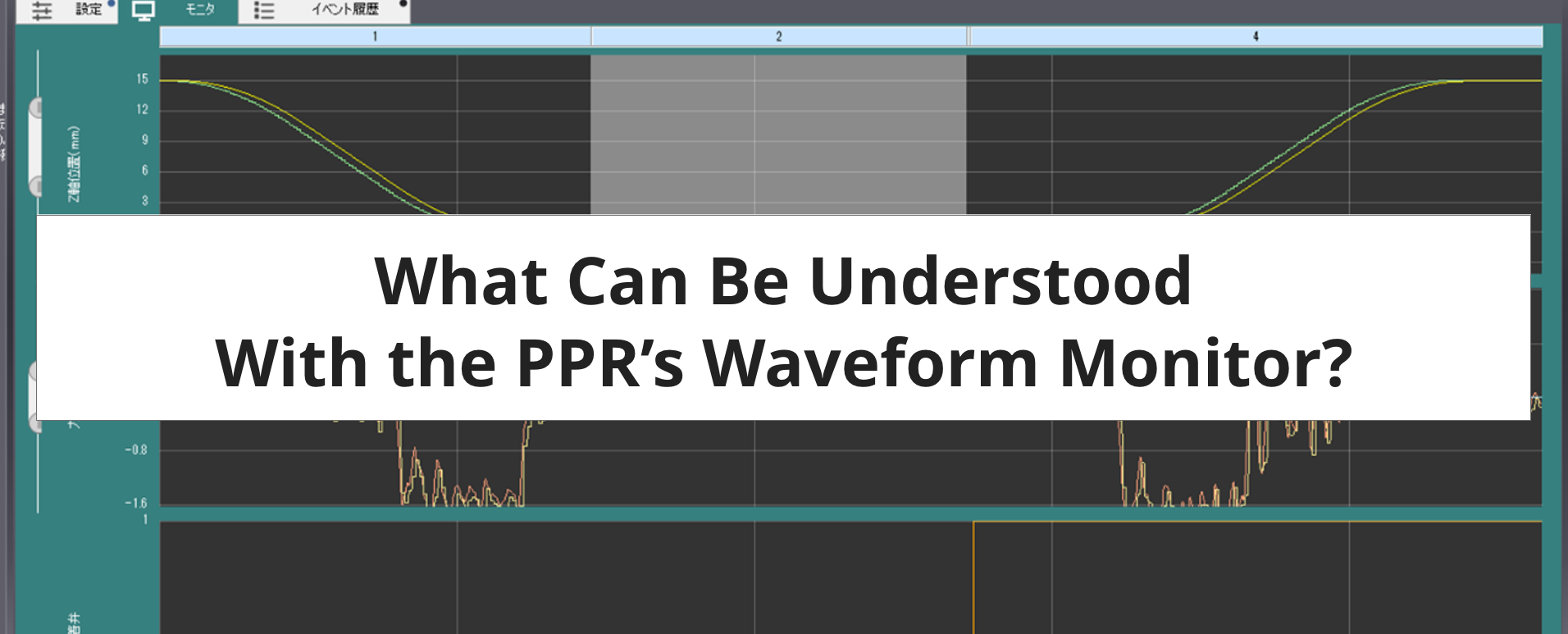
Introduction
You can setup, perform trial runs, and monitoring on the PPR using the dedicated T-ACT PC application. This is a free tool that can be downloaded from our website. What can you understand with the waveform monitor function that can be used with T-ACT? We've found that it's difficult to conceptualize before actually using it.
Therefore, we would like to introduce the details of a picking operation using position control and a picking operation using contact stop as an example of what can be understood from the waveforms obtained by actually operating the PPR.
Sequence Operation with the PPR
Before introducing the details of the waveform data, we think it is necessary to explain the PPR's sequence operation.
The PPR has seven functional modules: the Z axis, the θ axis, the force sensor, the pressure sensor, the flow rate sensor, the air drive (vacuum valve and release valve operation), and the Z axis encoder (Z axis position judgment). With T-ACT, these modules can be programmed to operate in tandem. For example, the template "Picking operation" that can be selected in the "Create new sequence" function performs the following operations.
1. Z Axis Step 1: Descends to the front of the workpiece at high speed
2. Z Axis Step 2: Contacts the workpiece with the contact stop function
3. Z Axis Step 3: Force control function presses the workpiece
4. Air Drive Step 1: Switches to negative pressure and opens the vacuum valve
5. Pressure Sensor Step 1: Judges whether the pressure has dropped to target threshold value
6. Z Axis Step 4: Ascends to standby position
7. Z Axis Encoder Step 1: Judges whether the target threshold was passed through during ascent
8. θ Axis Step 1: Performs rotation operation during ascent
For each of the above operations, various detailed parameters can be set.
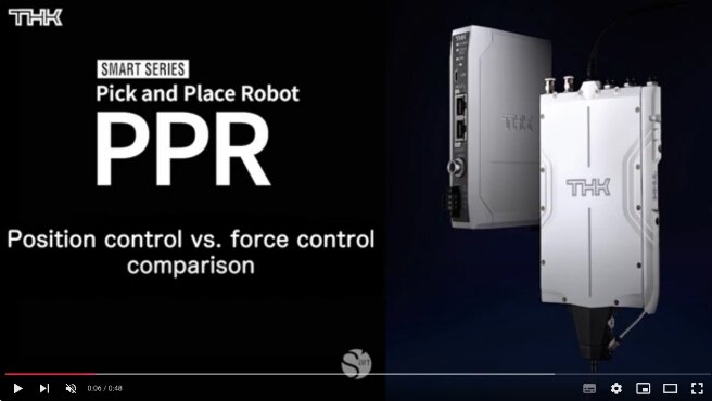
Below is a video showing a pick and place operation with positional control and a pick and place operation using contact stop.
Picking Operation Waveforms in Position Control
Now let's take a look at the picking operation waveform in position control.
The operations performed are as follows:
1. Z Axis Step 1: Descends to the workpiece at high speed
2. Air Drive Step 1: Switches to negative pressure and opens the air valve
3. Pressure Sensor Step 1: Judges whether pressure has dropped to the target threshold value
4. Z Axis Step 4: Ascends to the standby position
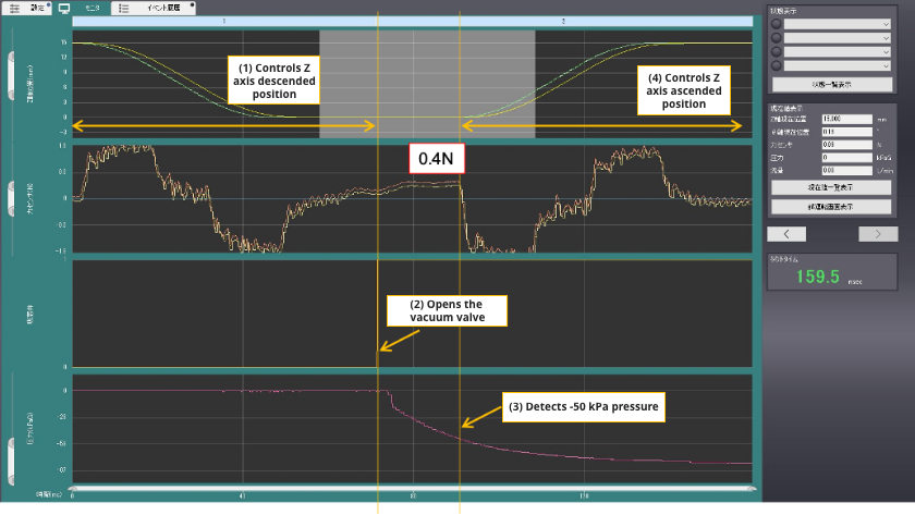
With this waveform, you can confirm the cylce time of the picking operation, the Z axis operation time, the time from opening the vacuum valve to the suction judgment, and the force sensor value at the low limit (impact force when contacting the workpiece). Cycle time can be shortened compared to the contact stop described below. It is better to use position control for customers that prioritize cycle time over workpiece damage.
- With this waveform, the force sensor detects a load of 0.4 N. However, in reality, the load could be 0 N when in a position that is not contacting the workpiece, or it could be several newtons, depending on the amount of force applied to the workpiece.
Picking Operation Waveforms Using Contact Stop
Now let's take a look at the picking operation waveform when using the PPR's contact stop function.
The operations performed are as follows:
1. Z Axis Step 1: Descends to the front of the workpiece at high speed
2. Z Axis Step 2: Makes contact with the workpiece using the contact stop function
3. Z Axis Step 3: Force control function presses the workpiece
4. Air Drive Step 1: Switches to negative pressure and opens the vacuum valve
5. Pressure Sensor Step 1: Judges whether the pressure has dropped to the target threshold value
6. Z Axis Step 4: Ascends to the standby position
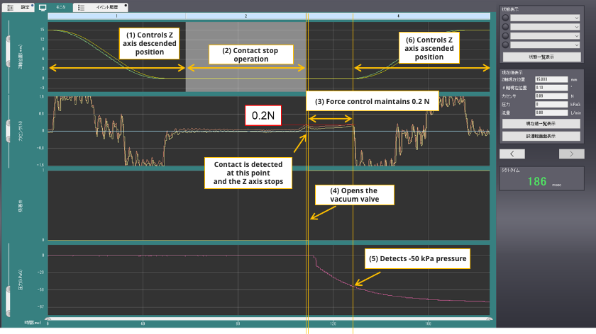
With this waveform, you can confirm the cycle time of the picking operation, the Z axis operation time, the time from opening the vacuum valve to suction judgment, the behavior at contact stop, and the force maintained by force control. When compared to the waveform during position control, we can see that the contact stop and force control operations are added, and although the cycle time is slower, the impact on the workpiece is reduced to 0.2 N.
What Can Be Achieved by Checking the Waveform Data
What can be achieved by checking these two waveform data?
By comparing the two waveforms shown, we can compare cycle time and impact force.
If the sequence were to stop mid-process, the waveform at the time of the error can be obtained, which can be used to improve the process by providing information such as how far the sequence progressed, whether contact was made with the workpiece, or whether the pressure dropped, and so on. It can also be used to get hints about which parts of the sequence can be shortened to further reduce cycle time.
In this article, we gave an overview of what could be understood by performing waveform analysis using T-ACT, but during actual use and operation, if you have any requests such as information on how to use T-ACT, clues to shorten cycle times, or how to analyze waveforms at the time of errors to identify causes, please feel free to contact us.