
This is a helpful overview for people unfamiliar with linear guides (linear motion guides) and those who are considering making a selection or purchase.
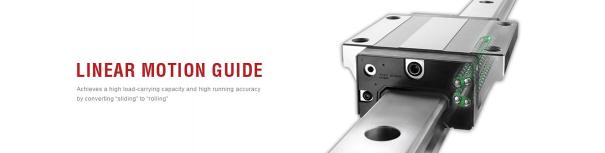
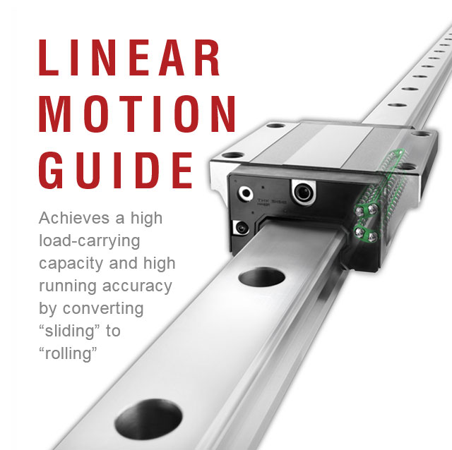
What Is a Linear Guide (Linear Motion Guide)?
Terminology and Difference from Rotary Bearings
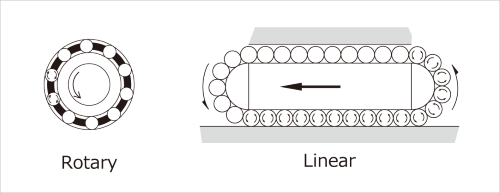
A linear guide is a machine element that utilizes bearings, which were developed for rotary motion, in order to move heavy objects easily in a straight line. It is referred to as a “recirculating linear ball bearing” by ISO and JIS, and “linear guideway” by the Japan Machine Tool Builders’ Association. THK CO., LTD. calls this the LM Guide (Linear Motion Guide). Other names like “linear motion ball guide” exist, and it is even referred to as a “linear bearing” in the sense that it is a bearing for linear motion as opposed to rotary motion.
Structure of the LM Guide
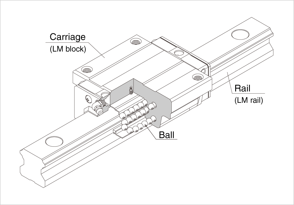
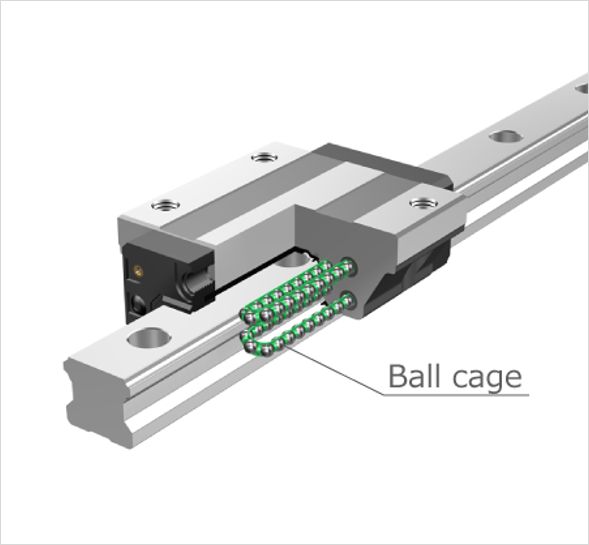
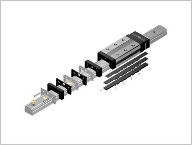
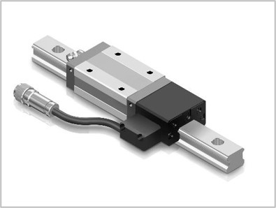
The linear guide largely comprises three components: a mobile carriage, a rail that supports the movements of the carriage, and balls. Linear motion is enabled by attaching a mechanism for recirculating the balls.
THK’s LM Guide refers to these parts as the LM block and LM rail.
History of the LM Guide
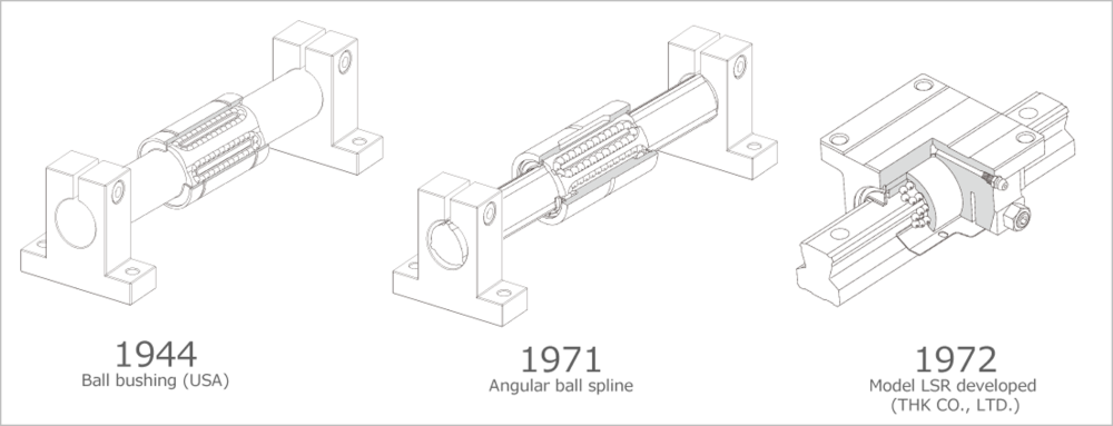
The history of the linear guide goes back to 1944, when the ball bushing was developed in the United States as the first linear motion rolling guide. The ball bushing contains balls as rolling elements between a cylindrical shaft and sleeve type nut. The balls recirculate with the movement of the nut, which enables infinite linear motion. A problem with the ball bushing was that the load capacity was low because the balls make point contact with the shaft and nut, and the contact surface area is small. In addition, the nut rotates when a moment (torque) acts on the shaft, which means two or more shafts become necessary to keep it from moving out of the travel direction. This presented an obstacle to compact machine design.
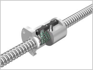
The ball spline was developed to overcome these challenges, featuring arc-shaped raceways ground into the shaft and nut. This changed the point contact between the balls and raceways into surface contact, which enables the ball spline to bear larger loads than the ball bushing. In addition, because the balls are contained between the raceway surfaces on the shaft and nut, the nut is prevented from rotating on the shaft. This meant only one shaft was needed to guide linear motion, and it could transmit torque.
The first ball spline had a problem with clearance occurring, and it was the search for a solution that led Hiroshi Teramachi (the founder of THK CO., LTD.) to develop the angular ball spline in 1971. The angular ball spline features protrusions on the nut and shaft raceways to provide angles that press on the balls, which eliminate the clearance that occurred with the conventional ball spline.
Compared to the ball bushing, the ball spline drastically increased the load capacity and provided smoother, clearance-free motion. However, because it was used with the shaft fixed on both ends, there were times when the ball spline could not support its true potential capacity during practical use, so its applications were limited. Then in 1972, Hiroshi Teramachi cut the ball spline nut and used that freed-up space to mount the shaft on a base, thus creating the linear motion ball guide. The world’s first linear motion ball guide (linear guide) was the Model LSR. By attaching a base, the ball spline shaft that used to float in the air when both ends were secured was now integrated with the mounting surface as a rail, which eliminated the loss in precision caused by deflection. In addition, the creation of a single block by fixing a housing onto the nut made handling easier because mounting from the top became possible just like it was with the rail. This became the basic form of the modern linear guide.
Later in 1973, THK developed the Model NSR-BC by combining the spline shaft and mounting base into the LM rail. Further improvements and combining the spline nut and housing into the LM block led to the development of the Model NSR-BA in 1975.
- 1944 Ball bushing (USA)
- 1971 Angular ball spline (Hiroshi Teramachi, founder of THK CO., LTD.)
- 1972 Model LSR, the world’s first LM Guide (Linear Motion Guide) linear guide (developed by THK CO., LTD.)
- 1973 Model NSR-BC with combined rail (developed by THK CO., LTD.)
- 1975 Model NSR-BA with combined block (developed by THK CO., LTD.)
Linear Guide Applications
Linear guides play the role of easily and smoothly guiding linear motion while bearing loads in order for machines to operate precisely and efficiently. They are an indispensable part of linear components in devices such as machine tools and semiconductor manufacturing equipment. Recently, they have also been used in railway vehicles, buses, automatic doors, seismic isolation systems, and other consumer fields.
Industrial Applications
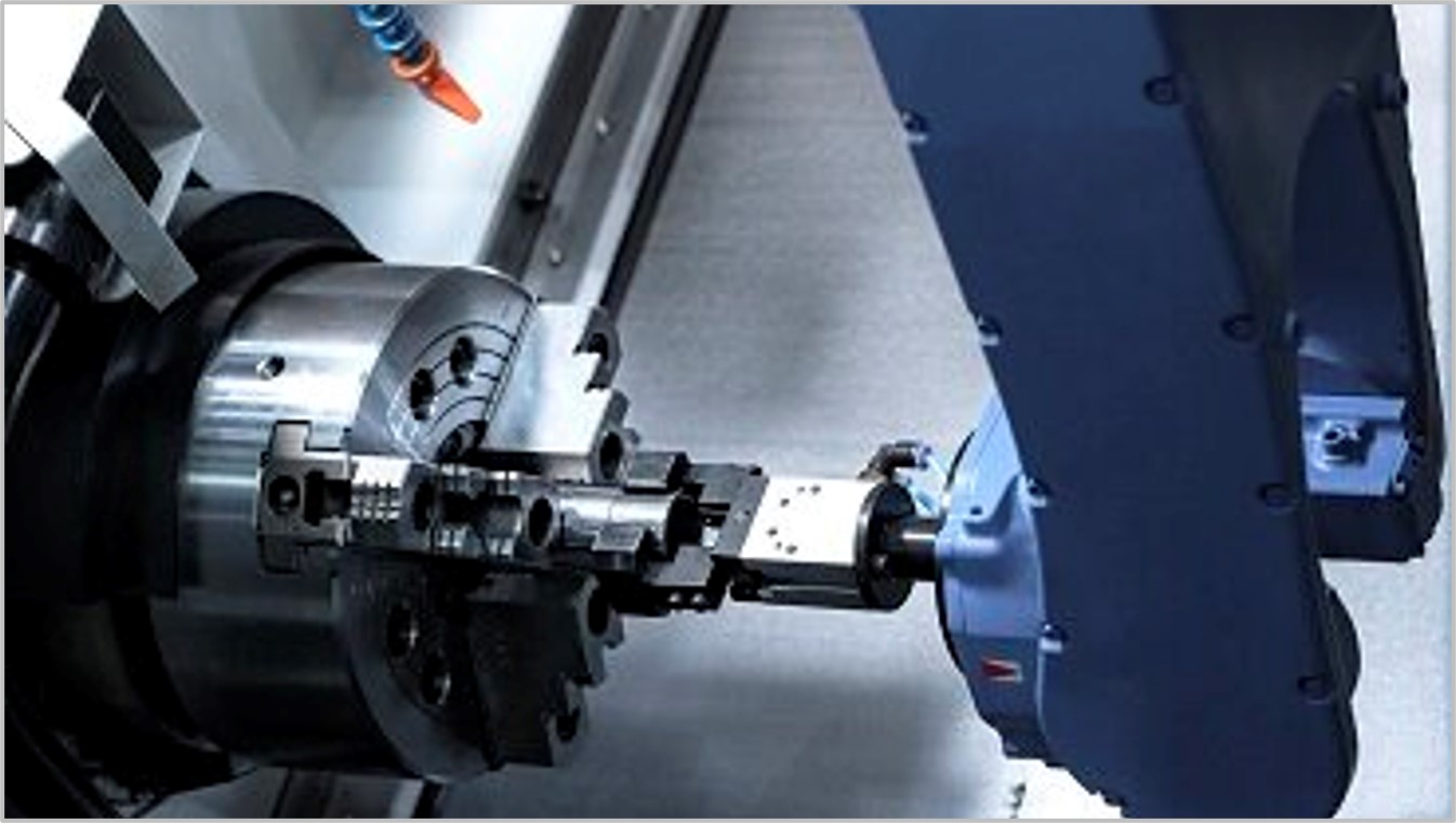
Machine tools
THK’s linear motion systems contribute to the guide portions that determine the machining accuracy of machine tools.
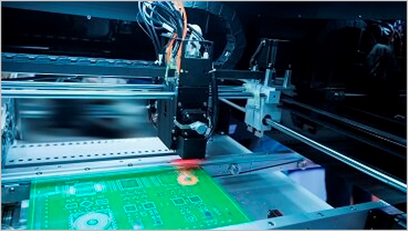
Precision Machinery
THK products are making great contributions to the ability of precision instruments to detect very fine movements and changes.
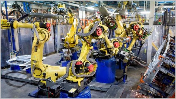
Industrial robots
THK products grant robot joints superior precision, rigidity, and high-speed performance.
Linear Guide Mechanism (Linear Motion System)
Linear guide mechanisms (linear motion systems) are used to move or position objects along a straight line with precision. Their main functions are split between guiding and driving elements. In particular, they refer to a system made up of machine elements that utilize rolling technology to move objects accurately in a straight line. The linear guide is one machine component that can be used for the guiding element.
Some of the many other possibilities include ball splines, linear bushings, slide rails, and cross-roller guides.
The driving element can be a machine element that converts torque from a motor into linear thrust, such as a ball screw or belt, or it could be hydraulics, pneumatics, or a linear motor. These components are combined in the mechanism design to achieve the precision, speed, and load requirements for the application. These mechanisms were developed around machine tools in particular, and they have been adopted for use in other types of industrial machinery as well as linear motion parts in consumer fields. “Linear motion system” is a registered trademark of THK CO., LTD. We also provide a lineup of machine elements that utilize the linear motion system to enable other types of motion such as arcs, or to combine linear and curved motion.
Linear Guide Characteristics
Light movement with no clearance
As linear guides are rolling guides, they have no clearance and lighter movements than sliding guides.
Infinite linear motion is possible
Rolling guides such as cross-roller guides and ball guides have finite strokes, but the linear guide’s balls recirculate endlessly, which means that the stroke can extend to however long the rail is made.
High permissible load
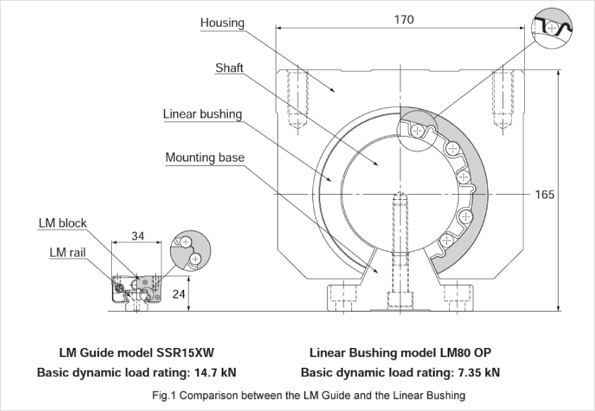
The linear guide’s raceways are curved grooves, which provide surface contact between the balls and raceways. This makes the permissible load about 13 times greater than that of guide components with point contact, such as the linear bushing. As a result, a linear guide can achieve a similar permissible load as a point-contact type through a more compact design.
THK’s LM Guide Technology
THK’s Long-Refined, Widely Adopted Core Technology
THK has been cultivating its technical expertise ever since 1972, when it developed the LM Guide and other linear motion systems. Even now, that core technology continues to redefine industry standards and enables THK to satisfy an ever-growing range of needs. These systems take the rotary principles of deep-groove ball bearings, the most economical and easy-to-use rotary bearings, and apply them to linear motion components.
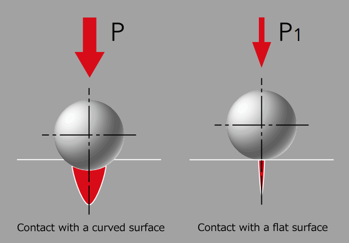
By using balls and rounded grooves of approximately equal diameters, THK has been able to change how the balls and grooves contact one another, moving away from point contact and closer to surface contact. As a result, THK has been able to increase a ball’s permissible load by approximately 13 times as compared to a ball of the same diameter in a traditional linear motion bearing. The service life is also extended by a factor of 2,200. (The permissible load P in the diagram is 1.3 times that of P1.)
LM Guide Variations
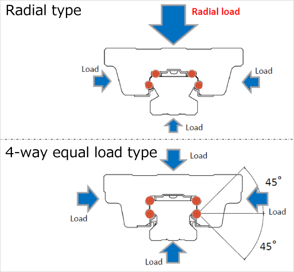
Many variations of the LM Guide are available to suit diverse applications. There are different categories of how loads are distributed, such as the radial load and four-way equal load types; categories based on shape, such as wide and miniature types; and more. In addition, the LM Guide featuring THK’s proprietary ball cage system helps improve equipment performance.
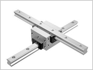
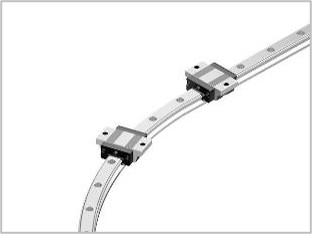
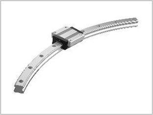
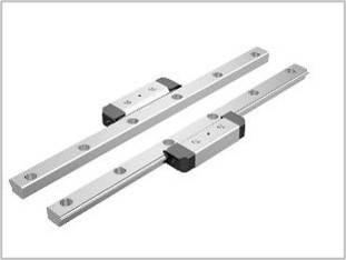
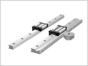
In addition, the product lineup also includes products that were developed from linear motion guide mechanisms, including non-linear products such as cross guides and curved guides, separate type products with two separated LM Guide units, and models with integrated gears.
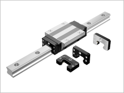
LM Guide Accessories
One thing that can damage the LM block is the intrusion of foreign materials. THK offers accessories that suit a variety of conditions, including dust, cutting chips, and spatter. Foreign materials can also be prevented from entering via the rear surface of the block. Another cause of damage is insufficient lubrication, and to address this issue, THK offers lubrication devices that extend the maintenance interval for replenishing lubricant. There are also some LM Guide products available that come with an integrated linear encoder.
THK’s LM Guide Production Structure
In the belief that the optimal place to manufacture products is the location of demand, THK manufactures the LM Guide at four factories in Japan (Yamaguchi, Yamagata, Gifu, and Mie) in addition to production facilities around the world.
THK also creates products with unique specifications in addition to the lineup available in the catalog. Let us know if the items in the catalog do not meet your needs, and we will investigate options for you.

Related Products
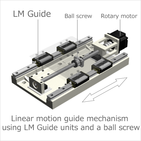
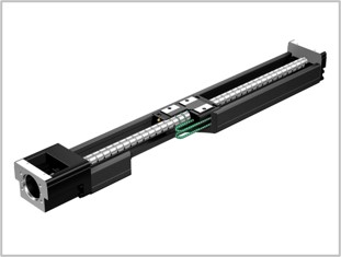
The LM Guide does not move on its own and requires some kind of power source. It can be moved by hand, but it is intended to be moved through mechanical means. Combining the LM Guide with a ball screw or another drive component will enable it to move the desired object easily and smoothly. In addition to single LM Guide units, THK also manufactures actuators that combine an LM Guide with a drive element.
OMNIedge: IoT-Enabled Predictive Failure Detection

OMNIedge is THK’s IoT service for manufacturing. This service eliminates the time and money it takes to select a sensor, develop an algorithm, and set up a network environment so it can be used right away. It is currently available not only for the LM Guide, but ball screws and actuators as well.
Convenient Services for Selection and Design


THK Online Services are available for free, and are only available to registered members.
The services help to solve problems related to manufacturing by offering customers a wealth of content that supports total lead time reduction and business efficiency. They also support our customers’ production activities through e-mails with the latest information, a product bookmark function, a function for comparing dimensional drawings and tables, and a tool that proposes optimal products from simple condition inputs. In addition, these services provide a wide range of technical information, from basic product data to selection and maintenance methods. There is even an upgraded service that provides customers with personalized information.
(As of November 27, 2023, the functions of the Technical Support Site were merged with those of the new website to form THK Online Services.)
* There are two types of member (full member and guest member). Learn more
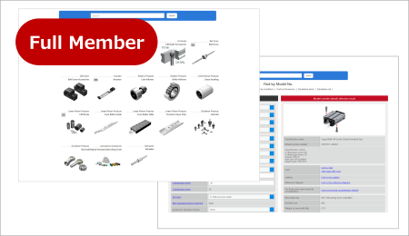
Product information for LM Guides (Linear Guides)
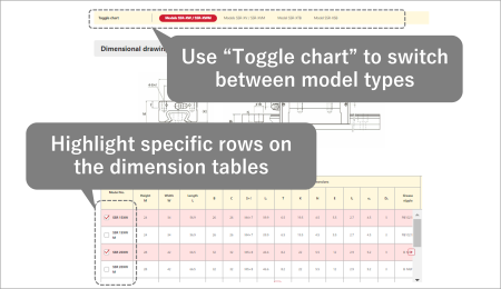
Members can view dimensional drawings and tables, as well as detailed product specifications. Use “Toggle chart” to switch between model types and quickly see the dimensional drawing or table you want to view.
You can also highlight specific rows on the dimension tables to easily compare multiple model types.
Tools to support product selection and design!
* There are two types of member (full member and guest member). Learn more
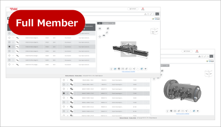
Designer (formerly called the Optimal Product Selection Tool)
An online tool for efficient model selection, service life calculation, and CAD data acquisition.
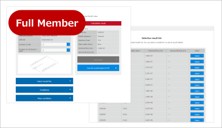
It will reduce the total lead time of equipment design. Product service life can be calculated based on usage conditions for a broad lineup of LM Guide, ball screw, and electric actuator products. It's easy to save the results of these calculations (10 items), write them to PDF sheets, and recalculate by calling up past results. We can even propose appropriate product models based on the results of service life calculations.
Mounting Methods and Maintenance
Mounting Methods
There are two main steps to mounting an LM Guide.
- Mounting the LM rail
- Mounting the LM block
The most common configuration is a two-axis layout. There are several ways the second (subsidiary) axis can be set up.
- Using a straightedge
- Using the parallelism of the table
- Having the subsidiary LM rail follow the master LM rail
- Using a jig
Maintenance
Lubrication is crucial for the proper functioning of the LM Guide.
LM Guide lubrication method
The THK Online Services features the following documents, which are intended to help extend the service life of the LM Guide.
Technical information: LM Guide inspection tips to extend the service life
Technical information: Signs an LM Guide needs replacement
Grease
The LM Guide’s performance can be maximized by using the right lubricant based on the application and purpose.
Lubricant can be split into the following general categories.
- Grease lubricant
- Oil lubricant
Each of these types of lubricant have their own special characteristics.
Lubrication Accessory Series for LM Systems
You can download the SDS (Safety Data Sheet) for the grease used to lubricate a product from the THK Online Services.