Designing the Guide System
THK offers various types of LM Guide in order to accomodate diverse operating conditions. Supporting ordinary horizontal, vertical, inverted, and slanted installation, as well as wall mounting and single-axis applications capable of recieving a moment, the wide array of LM Guide types makes it easy to obtain a linear guide system with a long service life and high rigidity while minimizing the required space for installation.
However, it is necessary to consider the position of the grease nipple or piping joint on the LM block in the context of the overall mounting orientation.
If the mounting orientation is other than horizontal, the lubricant may not reach the raceway completely. Be sure to let THK know the mounting orientation and the exact position in each LM block where a grease nipple or piping joint should be attached.
Even in an LM Guide with seals, the internal lubricant gradually seeps out during operation. Therefore, the system needs to be lubricated at an appropriate interval according to the operating conditions.
For the mounting orientation and the lubrication, see Conditions of the LM Guide and Lubrication, respectively.
Examples of Guide System Arrangements
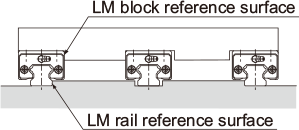
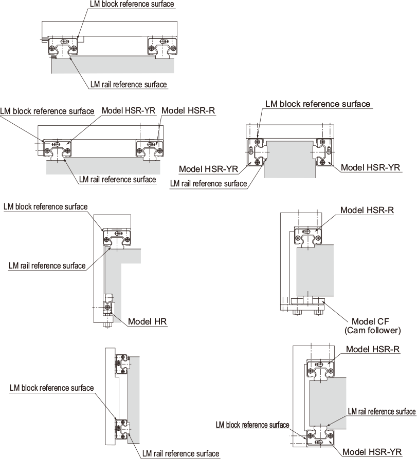
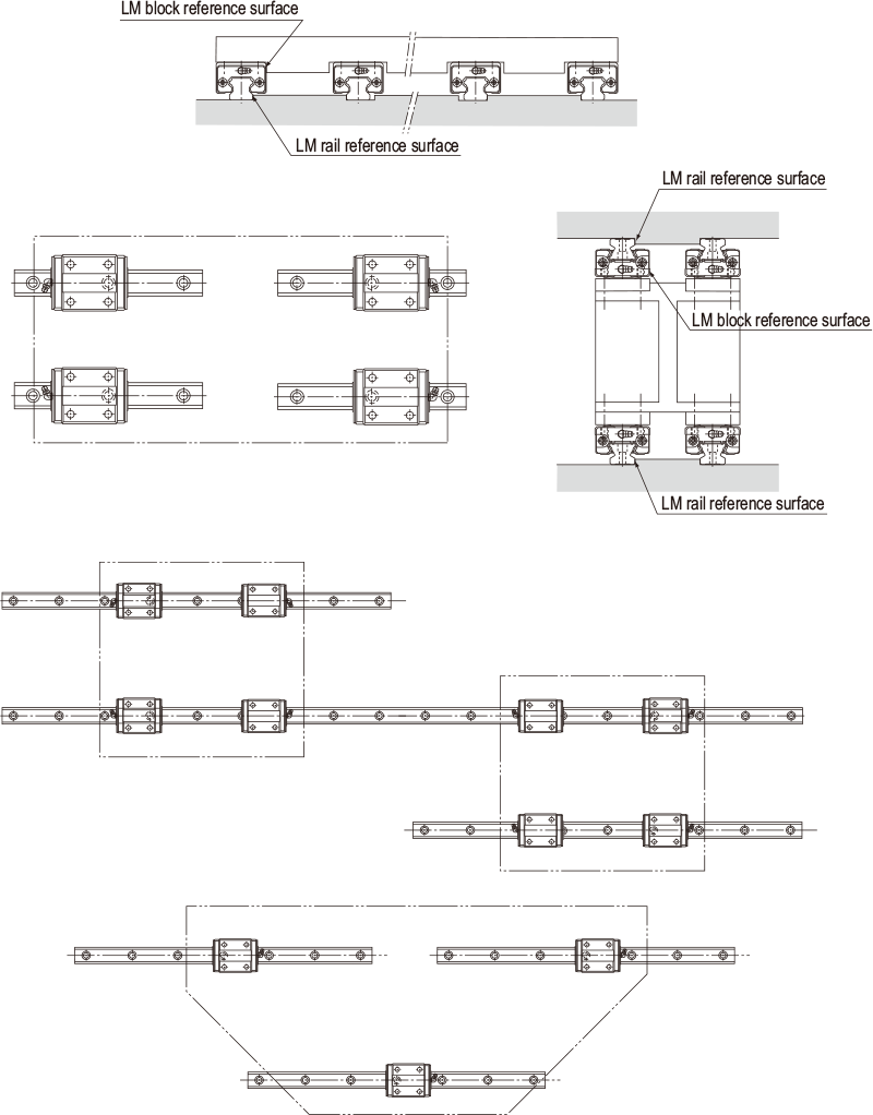
The following are representative guide systems and arrangements for installing an LM Guide. (For indication of the reference surface, see Master LM Guide Indicators and Combined Use )
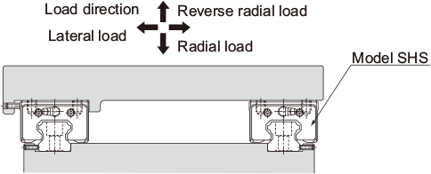
| Double-rail configuration when high rigidity is required in all directions | |
|---|---|
 |
|
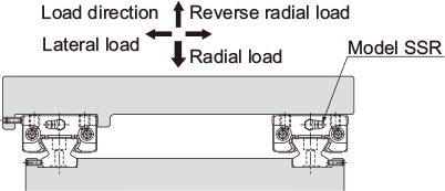
| Double-rail configuration when high rigidity is required in the radial direction | |
 |
|
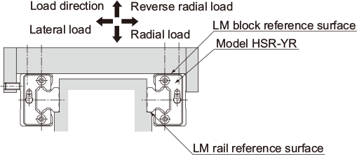
| When high rigidity is required in all directions and the installation space is limited in height | |
 |
|
| Single-rail configuration | |
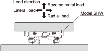 |
|
| When the minimum possible height of the equipment is allowed (adjustable preload type) | |
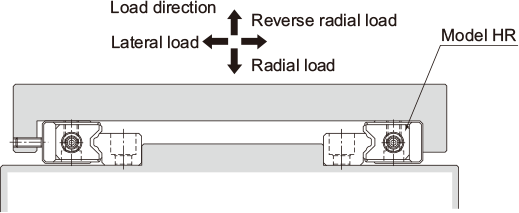 |
|
| When a medium load is applied and the mounting surface is rough (preload, self-adjusting type) | |
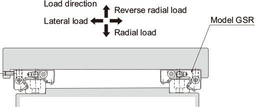 |
|
| Single-rail configuration | Triple-rail configuration |
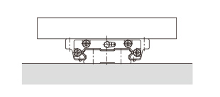 |
 |
| Double-rail configuration | |
 |
|
| Multi-rail configuration | |
 |
|
Methods for Securing an LM Guide to Based on Operating Conditions
LM Guide models are categorized into two groups by their mounting space and structure: types that are mounted with bolts from the top, and types that are mounted from the bottom. LM rails are also divided into types secured with bolts and those secured with clamps (model JR). This wide array of
types allows you to select a model that best suits your application.
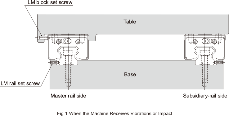
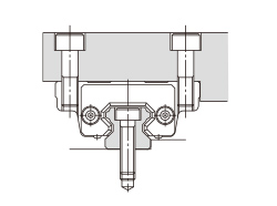
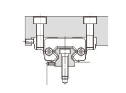
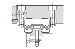
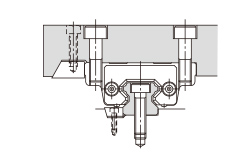
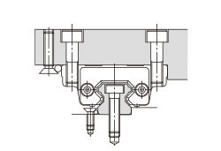
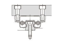
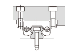
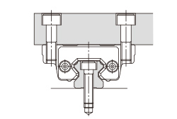
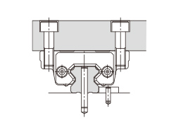
There are several ways to mount an LM Guide as shown in Table 1. When the machine is subject to vibrations that may cause the LM rails or LM blocks to loosen, we recommend the securing method indicated by Fig. 1. (If two or more rails are used in parallel, only the LM block on the master rail should be secured from the side.) If this method is not applicable for a structural reason, hammer in knock pins to secure the LM blocks as shown in Table 2. When using knock pins, machine the top and bottom surfaces of the LM rail by 2 mm to 3 mm using a carbide end mill before drilling the holes since the surfaces are hardened.
| (a) Secured only with side reference surfaces | (b) Secured with set screws |
|---|---|
 |
 |
| (c) Secured with a presser plate | (d) Secured with tapered gibs |
 |
 |
| (e) Secured with pins | |
 |
|
| (a) Secured only with the side reference surface of the rail | (b) Secured only with the side reference surface of the block |
|---|---|
 |
 |
| (c) Secured without a side reference surface | (d) Secured with dowel pins |
 |
 |