Designing a Mounting Surface
Designing a Mounting Surface
If particularly high accuracy is required for the machine to which an LM Guide is to be mounted, it is necessary to mount the LM rail with high accuracy. To achieve the desired accuracy, be sure to consider the following points when designing the mounting surface.
Corner Shape
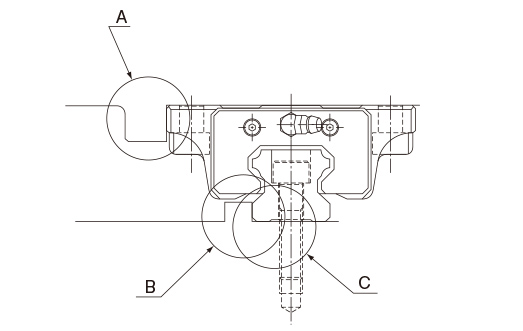
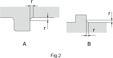
If an LM rail or LM block is mounted to a surface that has corners machined with a larger curved radius than the chamfer dimension of the LM rail or LM block, then the surface of the rail or the block may not make proper contact with the mounting surface. Therefore, when designing a mounting surface, it is important to carefully read the description of the “corner shape” for the subject model. (Fig. 2)
Perpendicularity with the Reference Surface
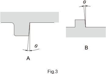
If the perpendicularity between the surface to which the LM rail or LM block will be mounted and the reference surface is not accurate, then the surface of the rail or the block may not make proper contact with the reference surface. Therefore, it is important to take into account the error in the perpendicularity between the mounting surface and the reference surface. (Fig. 3)
Dimensions of the Reference Surface
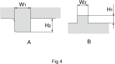
When designing the reference surface, be sure to take its height and thickness into account. If the reference surface is too high, it may interfere with the LM block. If it is too low, the LM rail or the LM block may not closely contact the mounting surface depending on the chamfer of the rail or the block. Additionally, if the reference surface is too thin, the desired accuracy may not be obtained due to poor rigidity when a lateral load is applied or when performing positioning using a lateral mounting bolt. (Fig. 4)
Dimensional Tolerance between the Reference Surface and the Mounting Holes
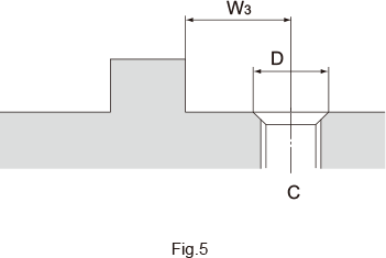
If the dimensional tolerance between the reference surface for the LM rail or the LM block and the mounting holes is too large, the rail or the block may not closely contact the surface of the base when mounted.
Normally, the tolerance should be within ±0.1 mm depending on the model. (Fig. 5)
Chamfer of the Tapped Mounting Hole
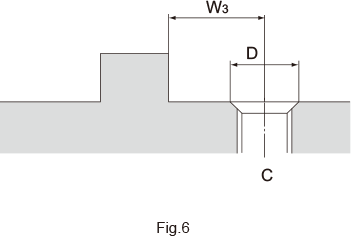
To mount the LM rail, the mounting surface needs to be tapped and the tapped hole has to be chamfered. If the chamfer of the tapped hole is too large or too small, it may affect the accuracy. (Fig. 6)
Guidelines for the chamfer dimension: Chamfer diameter D = nominal diameter of the bolt + pitch
Example: Chamfer diameter D with M6 (pitch): D = 6 + 1 = 7
Master LM Guide Indicators and Combined Use
Master LM Guide Indicators
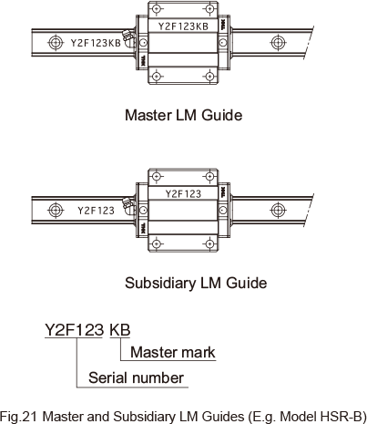
All LM rails mounted on the same plane are marked with the same serial number. The LM rail marked with "KB" after the serial number is the master LM rail. The LM block on the master LM rail has its reference surface finished to a designated precision, allowing it to serve as the positioning reference for tables (see Fig. 21). Normal grade LM Guide units are not marked with "KB." Therefore, any one of the LM rails having the same serial number can be used as the master LM rail.
Reference Surface Indicators
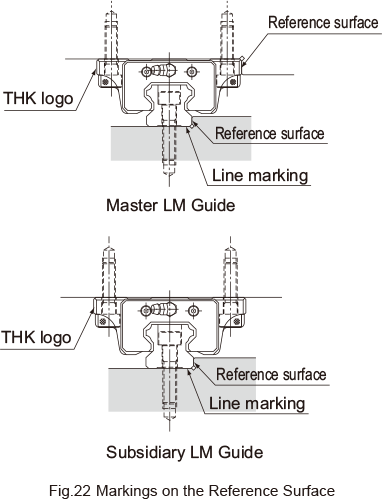
In the LM Guide, the reference surface of the LM block is opposite the surface marked with the THK logo, and that of the LM rail is on the surface marked with a line (see Fig. 22). Please specify if it is necessary to reverse the reference surface of the LM rail and block, or if the grease nipple must be oriented in the opposite direction.
Serial Number Marking and Combined Use of an LM Rail and LM Blocks
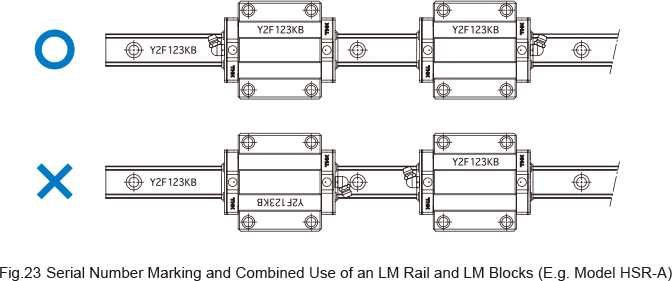
An LM rail and LM block(s) used in combination must have the same serial number. When removing an LM block from the LM rail and reinstalling the LM block, make sure that they have the same serial number and the numbers are oriented in the same direction (see Fig. 23).
Use of Joint Rails
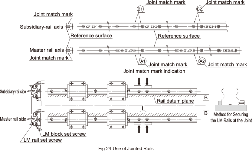
When a long LM rail is ordered, two or more rails will be joined together to the desired length. When joining rails, make sure that the joint match marks shown in Fig. 24 are correctly positioned. When two LM Guide units with joint rails are to be arranged parallel to each other, they will be manufactured so that they have axial symmetry (are mirror images of each other) as a set.