Average Load
In cases where the load applied to each LM block fluctuates under different conditions, such as an industrial robot advancing while holding a workpiece with its arm then retreating with its arm empty, or a machine tool handling various workpieces, it is necessary to calculate the service life of the LM block while taking into account such fluctuating loading conditions. The average load (Pm) is the load under which the service life of the LM Guide is equivalent to that under varying loads applied to the LM blocks.
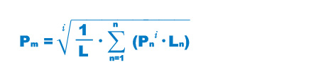
| Pm | Average load (N) |
|---|---|
| Pn | Varying load (N) |
| L | Total travel distance (mm) |
| Ln | Distance traveled under load Pn (mm) |
| i | Constant determined by rolling element |
Note: The above equation or the equation (1) below applies when the rolling elements are balls.
- With stepwise load fluctution

Pm Average load (N) Pn Varying load (N) L Total travel distance (mm) Ln Distance traveled under Pn (mm) 
Pm Average load (N) Pn Varying load (N) L Total travel distance (mm) Ln Distance traveled under Pn (mm) 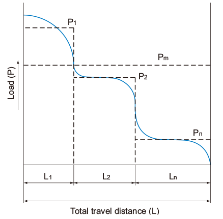
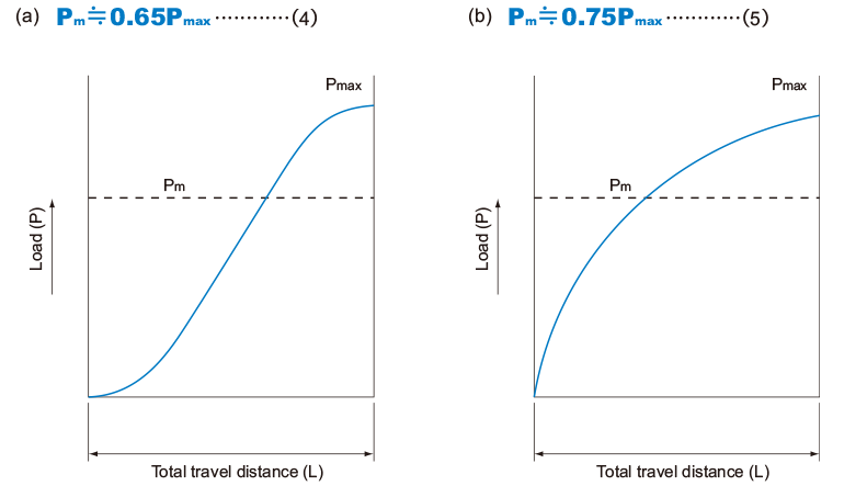
- With monotone load fluctuation
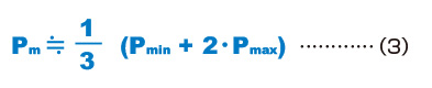
Pmin Minimum load (N) Pmax Maximum load (N) 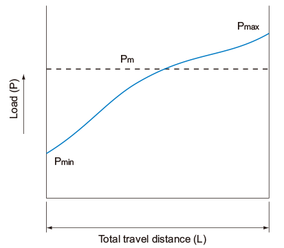
- With sinusoidal load fluctuation
Example of Calculating the Average Load (1)
- with Horizontal Mount and Acceleration/Deceleration Considered -
Conditions
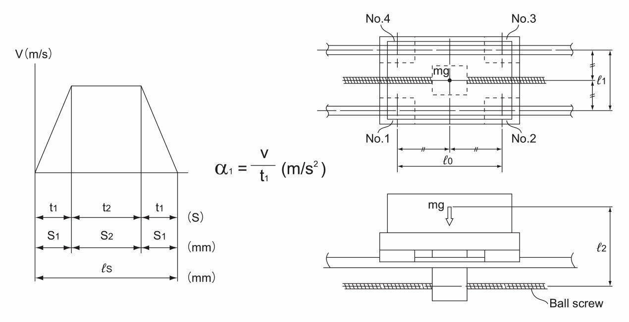
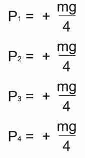
Load Applied to the LM Block
●During uniform motion
●During acceleration
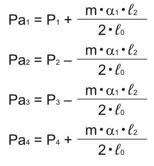
●During deceleration
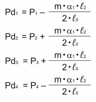
Average Load
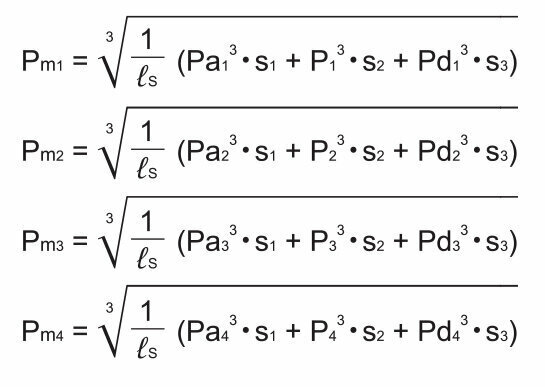
Note: Pan and Pdn represent loads applied to each LM block. The suffix “n” indicates the block number in the diagram above.
Example of Calculating the Average Load (2) - When the Rails are Movable
Conditions
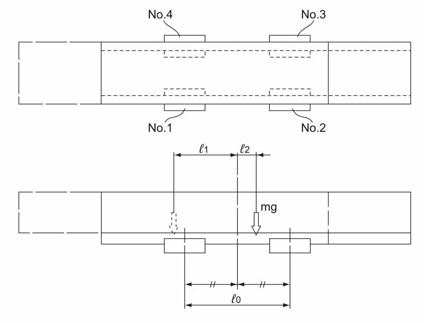
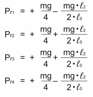
Load Applied to the LM Block
●At the left of the arm
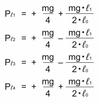
●At the right of the arm
Average Load
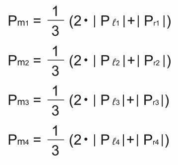
Note: Pℓn and Prn represent loads applied to each LM block. The suffix “n” indicates the block number in the diagram above.
