Studying the Service Life
Service Life of the Ball Screw
A Ball Screw in motion under an external load receives repeated stress on its raceways and balls.When the stress reaches the limit, the raceways break from fatigue, and their surfaces flake like scales. This phenomenon is called flaking. The service life of the Ball Screw is the total number of revolutions until the first flaking occurs on any of the raceways or the balls as a result of rolling fatigue of the material.
The service life of the Ball Screw varies from unit to unit even if they are manufactured in the same process and used in the same operating conditions. For this reason, when determining the service life of a Ball Screw unit, the nominal life as defined below is used as a guideline.
The nominal life is the total number of revolutions that 90% of identical Ball Screw units in a group achieve without flaking after they independently operate in the same conditions.
Calculating the Rated Life
The service life of the Ball Screw is calculated from the formula (32) below using the basic dynamic load rating (Ca) and the applied axial load.
Calculating the Nominal Life
The nominal life (L10) is obtained from the following formula using the basic dynamic load rating (Ca) and the applied load in the axial direction (Fa).

Calculating the Nominal Life
During use, a ball screw may be subjected to vibrations and shocks as well as fluctuating loads, which are difficult to detect. Taking these factors into account, the modified nominal life (L10m) can be calculated according to the following formula (32-2).

| Vibrations/impact | Speed (V) | fW |
|---|---|---|
| Faint | Very low V≦0.25 m/s |
1 to 1.2 |
| Weak | Slow 0.25<V≦1 m/s |
1.2 to 1.5 |
| Medium | Medium 1<V≦2 m/s |
1.5 to 2 |
| Strong | High V>2 m/s |
2 to 3.5 |
*The basic dynamic load rating (Ca) is used in calculations of service life when the ball screw is under an axial load.The basic dynamic load rating is defined as a load rating based on the movement of a set of identical ball screws with a rated life L=106rev, using a load applied in the axial direction that does not vary in either magnitude or direction. (The basic dynamic load ratings (Ca) for each model number are indicated in the specification tables.)
*The rated service life is estimated by calculating the load on the premise that the product is set up in ideal mounting conditions with the assurance of good lubrication. The service life can be affected by the precision of the mounting materials used and any distortion.
Service Life Time
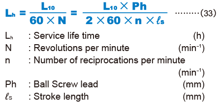
If the revolutions per minute is determined, the service life time can be calculated from the equation (33) below using the nominal life (L10).

Service Life in Travel Distance
The service life in travel distance can be calculated from the equation (34) below using the nominal life (L10) and the Ball Screw lead.

Applied Load and Service Life with a Preload Taken into Account
If the Ball Screw is used under a preload (medium preload), it is necessary to consider the applied preload in calculating the service life since the ball screw nut already receives an internal load. For details on applied preload for a specific model number, contact THK.
Average Axial Load
If an axial load acting on the Ball Screw is present, it is necessary to calculate the service life by determining the average axial load.
The average axial load (Fm) is a constant load that equals to the service life in fluctuating the load conditions.
If the load changes in steps, the average axial load can be obtained from the equation below.

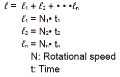
To determine the average axial load using a rotational speed and time, instead of a distance, calculate the average axial load by determining the distance in the equation below.

When the Applied Load Sign Changes
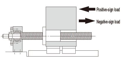
If the sign (positive or negative) used for variable load is always the same, there are no problems with formula (35). However, if the variable load sign changes depending on the type of operation, calculate the average axial load for either positive or negative load, allowing for the load direction. (If the average axial load for positive load is calculated, the negative load is taken to be zero.) The larger of the two average axial loads is taken as the average axial load when the service life is calculated.
Example: Calculate the average axial load with the following load conditions.
| Operation No. | Varying load Fa n (N) |
Travel distance ℓn(mm) |
|---|---|---|
| No.1 | 10 | 10 |
| No.2 | 50 | 50 |
| No.3 | -40 | 10 |
| No.4 | -10 | 70 |
*The subscripts of the fluctuating load symbol and the travel distance symbol indicate operation numbers.

Average axial load of positive-sign load
*To calculate the average axial load of the positive-sign load, assume Fa3 and Fa4 to be zero.

Average axial load of negative-sign load
*To calculate the average axial load of the negative-sign load, assume Fa1 and Fa2 to be zero.

Accordingly, the average axial load of the positive-sign load (Fm1) is adopted as the average axial load (Fm) for calculating the service life.
Point of Selection
- Conditions of the Ball Screw
- Conditions of the Ball Screw
- Estimating the shaft length
- Selecting lead・Selecting a shaft diameter
- Method for Mounting the Ball Screw Shaft
- Permissible Axial Load
- Permissible Rotational Speed
- Selecting a Nut
- Calculating the permissible axial load
- Studying the Service Life
- Studying the Rigidity
- Studying the Positioning Accuracy
- Studying the Rotational Torque
- Studying the Driving Motor