Studying the Rigidity
To increase the positioning accuracy of feed screws in NC machine tools or the precision machines, or to reduce the displacement caused by the cutting force, it is necessary to design the rigidity of the components in a well-balanced manner.
Axial Rigidity of the Feed Screw System
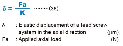
When the axial rigidity of a feed screw system is K, the elastic displacement in the axial direction can be obtained using the equation (36) below.
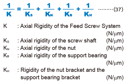
The axial rigidity (K) of the feed screw system is obtained using the equation (37) below.
Axial rigidity of the screw shaft
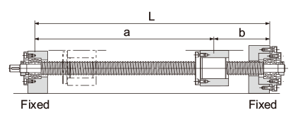
The axial rigidity of a screw shaft varies depending on the method for mounting the shaft.
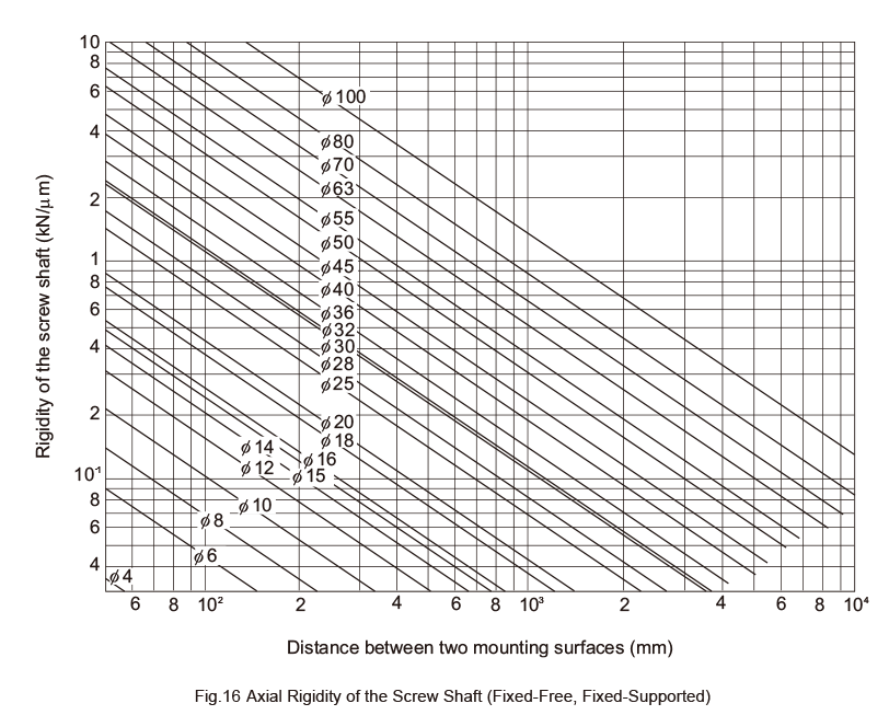
For Fixed-Supported (or -Free) Configuration
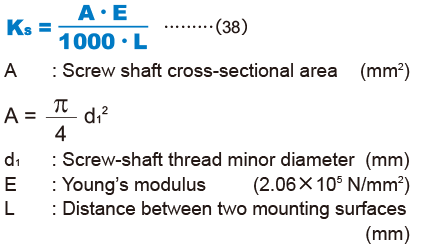
Fig.16 shows an axial rigidity diagram for the screw shaft.
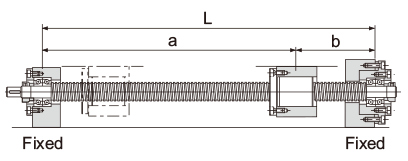
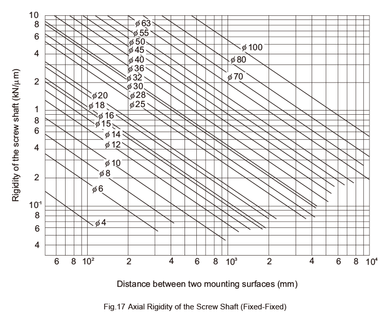
For Fixed-Fixed Configuration
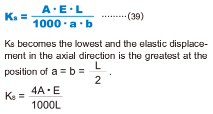
Fig.17 shows an axial rigidity diagram of the screw shaft in this configuration.
Axial rigidity of the nut
The axial rigidity of the nut varies widely with preloads.
No Preload Type
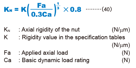
The logical rigidity in the axial direction when an axial load accounting for 30% of the basic dynamic load rating (Ca) is applied is indicated in the specification tables of the corresponding model number. This value does not include the rigidity of the components related to the nut-mounting bracket.In general, set the rigidity at roughly 80% of the value in the table.
The rigidity when the applied axial load is not 30% of the basic dynamic load rating (Ca) is calculated using the equation (40) below.
Preload Type
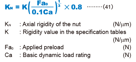
The logical rigidity in the axial direction when an axial load accounting for 10% of the basic dynamic load rating (Ca) is applied is indicated in the dimensional table of the corresponding model number.This value does not include the rigidity of the components related to the nut-mounting bracket. In general, generally set the rigidity at roughly 80% of the value in the table.
The rigidity when the applied preload is not 10% of the basic dynamic load rating (Ca) is calculated using the equation (41) below.
Axial rigidity of the support bearing
The rigidity of the Ball Screw support bearing varies depending on the support bearing used.
The calculation of the rigidity with a representative angular contact ball bearing is shown in the equation (42) below.
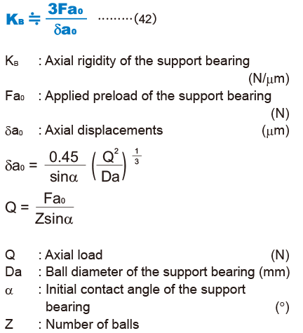
For details of a specific support bearing, contact its manufacturer.
Axial Rigidity of the Nut Bracket and the Support Bearing Bracket
Take this factor into consideration when designing your machine. Set the rigidity as high as possible.
Point of Selection
- Conditions of the Ball Screw
- Conditions of the Ball Screw
- Estimating the shaft length
- Selecting lead・Selecting a shaft diameter
- Method for Mounting the Ball Screw Shaft
- Permissible Axial Load
- Permissible Rotational Speed
- Selecting a Nut
- Calculating the permissible axial load
- Studying the Service Life
- Studying the Rigidity
- Studying the Positioning Accuracy
- Studying the Rotational Torque
- Studying the Driving Motor