Operating Conditions of the Ball Screw
Lead angle accuracy
The lead angle accuracy of the ball screw is controlled in accordance with the JIS standard JIS B 1192 (ISO 3408).
Accuracy grades C0 to C5 are defined in the linearity and the directional property, and C7 to C10 by error in relation to a 300 mm travel distance.
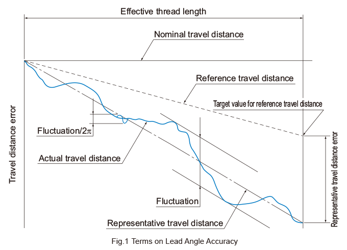
Actual Travel Distance
An error in the travel distance measured with an actual ball screw.
Reference Travel Distance
Generally, it is the same as nominal travel distance, but can be an intentionally corrected value of the nominal travel distance according to the intended use.
Target Value for Reference Travel Distance
You may apply tension in order to prevent screw shaft runout or set a negative or positive reference travel distance value in advance to account for possible expansion or contraction from an external load or temperature change. In such cases, indicate a target value for the reference travel distance.
Representative Travel Distance
Is a straight line representing the trend of the actual travel distance, and obtained with the least squares method from the curve that indicates the actual travel distance.
Representative Travel Distance Error (in ±)
Is the difference between the representative travel distance and the reference travel distance.
Fluctuation
Represents the maximum width of the actual travel distance between two straight lines drawn in parallel with the representative travel distance.
Fluctuation/300
Indicates a fluctuation in a given threaded portion of length of 300 mm.
Fluctuation/2π
Indicates the fluctuation in one revolution of the screw shaft.
| Precision Ball Screw | ||||||||||||||
|---|---|---|---|---|---|---|---|---|---|---|---|---|---|---|
| Rolled Ball Screw | ||||||||||||||
| Accuracy grades | C0 | C1 | C2 | C3 | C5 | C7 | C8 | C10 | ||||||
| Effective thread length |
Representative travel distance error |
Fluctuation | Representative travel distance error |
Fluctuation | Representative travel distance error |
Fluctuation | Representative travel distance error |
Fluctuation | Representative travel distance error |
Fluctuation | Travel distance error |
Travel distance error |
Travel distance error |
|
| Above | Up to | |||||||||||||
| - | 100 | 3 | 3 | 3.5 | 5 | 5 | 7 | 8 | 8 | 18 | 18 | ±50/300 mm | ±100/300 mm | ±210/300 mm |
| 100 | 200 | 3.5 | 3 | 4.5 | 5 | 7 | 7 | 10 | 8 | 20 | 18 | |||
| 200 | 315 | 4 | 3.5 | 6 | 5 | 8 | 7 | 12 | 8 | 23 | 18 | |||
| 315 | 400 | 5 | 3.5 | 7 | 5 | 9 | 7 | 13 | 10 | 25 | 20 | |||
| 400 | 500 | 6 | 4 | 8 | 5 | 10 | 7 | 15 | 10 | 27 | 20 | |||
| 500 | 630 | 6 | 4 | 9 | 6 | 11 | 8 | 16 | 12 | 30 | 23 | |||
| 630 | 800 | 7 | 5 | 10 | 7 | 13 | 9 | 18 | 13 | 35 | 25 | |||
| 800 | 1,000 | 8 | 6 | 11 | 8 | 15 | 10 | 21 | 15 | 40 | 27 | |||
| 1,000 | 1,250 | 9 | 6 | 13 | 9 | 18 | 11 | 24 | 16 | 46 | 30 | |||
| 1,250 | 1,600 | 11 | 7 | 15 | 10 | 21 | 13 | 29 | 18 | 54 | 35 | |||
| 1,600 | 2,000 | - | - | 18 | 11 | 25 | 15 | 35 | 21 | 65 | 40 | |||
| 2,000 | 2,500 | - | - | 22 | 13 | 30 | 18 | 41 | 24 | 77 | 46 | |||
| 2,500 | 3,150 | - | - | 26 | 15 | 36 | 21 | 50 | 29 | 93 | 54 | |||
| 3,150 | 4,000 | - | - | 30 | 18 | 44 | 25 | 60 | 35 | 115 | 65 | |||
| 4,000 | 5,000 | - | - | - | - | 52 | 30 | 72 | 41 | 140 | 77 | |||
| 5,000 | 6,300 | - | - | - | - | 65 | 36 | 90 | 50 | 170 | 93 | |||
| 6,300 | 8,000 | - | - | - | - | - | - | 110 | 60 | 210 | 115 | |||
| 8,000 | 10,000 | - | - | - | - | - | - | - | - | 260 | 140 | |||
| Accuracy grades | C0 | C1 | C2 | C3 | C5 | C7 | C8 | C10 |
|---|---|---|---|---|---|---|---|---|
| Fluctuation/300 | 3.5 | 5 | 7 | 8 | 18 | - | - | - |
| Fluctuation/2π | 3 | 4 | 5 | 6 | 8 | - | - | - |
| Type | Grade | Remarks |
|---|---|---|
| For positioning | 0, 1, 3, 5 | ISO compliant |
| For transport | 0, 1, 3, 5, 7, 10 |
Example: The following data were obtained by measuring the lead of a ball screw manufactured with a target reference travel distance of ‒9 μm/500 mm.
| Command position (A) | 0 | 50 | 100 | 150 |
|---|---|---|---|---|
| Travel distance (B) | 0 | 49.998 | 100.001 | 149.996 |
| Travel distance error (A-B) | 0 | -0.002 | +0.001 | -0.004 |
| Command position (A) | 200 | 250 | 300 | 350 |
|---|---|---|---|---|
| Travel distance (B) | 199.995 | 249.993 | 299.989 | 349.985 |
| Travel distance error (A-B) | -0.005 | -0.007 | -0.011 | -0.015 |
| Command position (A) | 400 | 450 | 500 |
|---|---|---|---|
| Travel distance (B) | 399.983 | 449.981 | 499.984 |
| Travel distance error (A-B) | -0.017 | -0.019 | -0.016 |
The measurement data are expressed in a graph as shown in Fig. 2.
The positioning error (A-B) is the actual travel distance while the straight line representing the trend of the (A-B) graph indicates the representative travel distance.
The difference between the reference travel distance and the representative travel distance appears as the representative travel distance error.
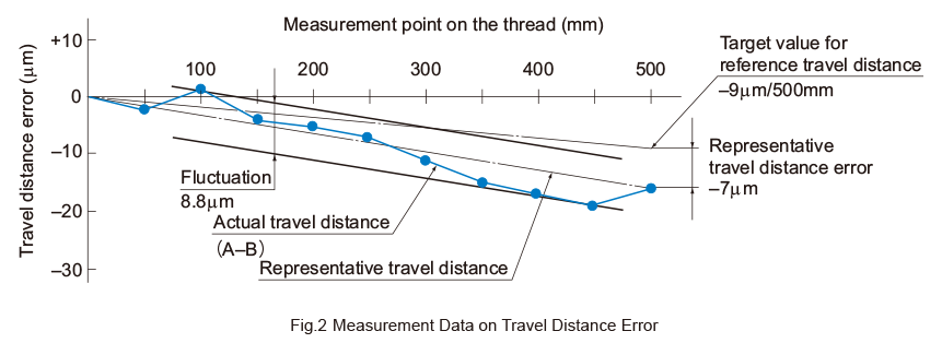
Measurements
Representative travel distance error: -7 μm
Fluctuation: 8.8 μm
Accuracy of the Mounting Surface
The accuracy of the ball screw mounting surface complies with the JIS standard JIS B 1192 (ISO 3408).
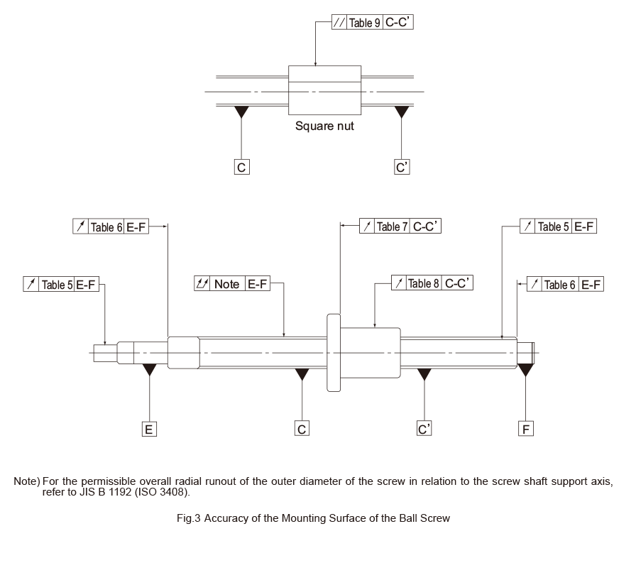
Accuracy Standards for the Mounting Surface
Table 5 to Table 9 show accuracy standards for the mounting surfaces of the precision ball screw.
Unit: μm
| Screw shaft outer diameter (mm) |
Runout (maximum) | ||||||
|---|---|---|---|---|---|---|---|
| Above | Or less | C0 | C1 | C2 | C3 | C5 | C7 |
| - | 8 | 3 | 5 | 7 | 8 | 10 | 14 |
| 8 | 12 | 4 | 5 | 7 | 8 | 11 | 14 |
| 12 | 20 | 4 | 6 | 8 | 9 | 12 | 14 |
| 20 | 32 | 5 | 7 | 9 | 10 | 13 | 20 |
| 32 | 50 | 6 | 8 | 10 | 12 | 15 | 20 |
| 50 | 80 | 7 | 9 | 11 | 13 | 17 | 20 |
| 80 | 100 | - | 10 | 12 | 15 | 20 | 30 |
Example: model No. DIK2005-6RRGO+500LC5
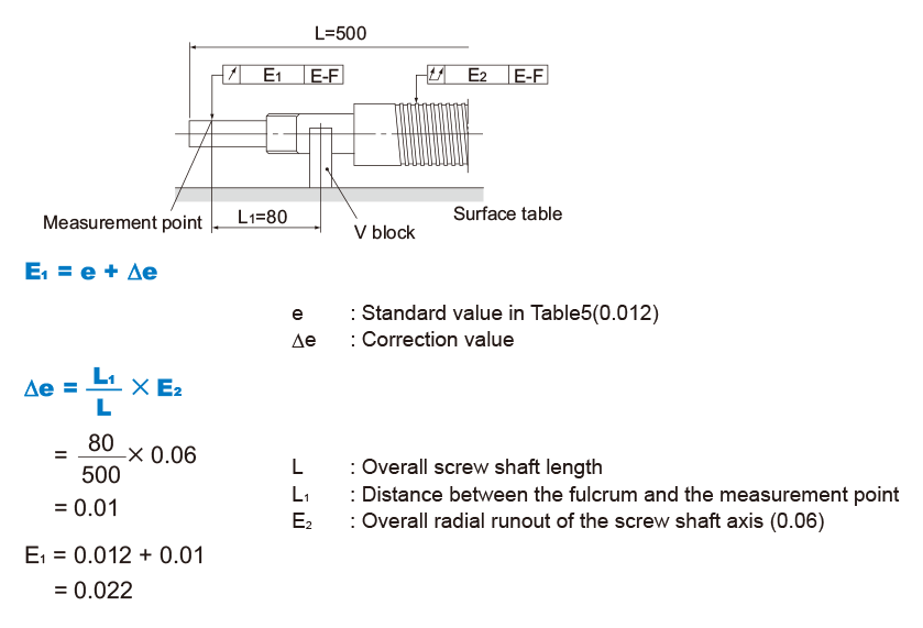
Note: For the permissible overall radial runout of the outer diameter of the screw in relation to the screw shaft axis at the journal, refer to JIS B 1192 (ISO 3408).
| Screw shaft outer diameter (mm) |
Permissible axial runout (maximum) |
||||||
|---|---|---|---|---|---|---|---|
| Above | Up to | C0 | C1 | C2 | C3 | C5 | C7 |
| - | 8 | 2 | 3 | 3 | 4 | 5 | 7 |
| 8 | 12 | 2 | 3 | 3 | 4 | 5 | 7 |
| 12 | 20 | 2 | 3 | 3 | 4 | 5 | 7 |
| 20 | 32 | 2 | 3 | 3 | 4 | 5 | 7 |
| 32 | 50 | 2 | 3 | 3 | 4 | 5 | 8 |
| 50 | 80 | 3 | 4 | 4 | 5 | 7 | 10 |
| 80 | 100 | - | 4 | 5 | 6 | 8 | 11 |
| Nut diameter (mm) | Permissible axial runout (maximum) |
||||||
|---|---|---|---|---|---|---|---|
| Above | Up to | C0 | C1 | C2 | C3 | C5 | C7 |
| - | 20 | 5 | 6 | 7 | 8 | 10 | 14 |
| 20 | 32 | 5 | 6 | 7 | 8 | 10 | 14 |
| 32 | 50 | 6 | 7 | 8 | 8 | 11 | 18 |
| 50 | 80 | 7 | 8 | 9 | 10 | 13 | 18 |
| 80 | 125 | 7 | 9 | 10 | 12 | 15 | 20 |
| 125 | 160 | 8 | 10 | 11 | 13 | 17 | 20 |
| 160 | 200 | - | 11 | 12 | 14 | 18 | 25 |
| Nut diameter (mm) | Permissible radial runout | ||||||
|---|---|---|---|---|---|---|---|
| Above | Or less | C0 | C1 | C2 | C3 | C5 | C7 |
| - | 20 | 5 | 6 | 7 | 9 | 12 | 20 |
| 20 | 32 | 6 | 7 | 8 | 10 | 12 | 20 |
| 32 | 50 | 7 | 8 | 10 | 12 | 15 | 30 |
| 50 | 80 | 8 | 10 | 12 | 15 | 19 | 30 |
| 80 | 125 | 9 | 12 | 16 | 20 | 27 | 40 |
| 125 | 160 | 10 | 13 | 17 | 22 | 30 | 40 |
| 160 | 200 | - | 16 | 20 | 25 | 34 | 50 |
| Mounting reference length (mm) |
Permissible parallelism | ||||||
|---|---|---|---|---|---|---|---|
| Above | Up to | C0 | C1 | C2 | C3 | C5 | C7 |
| - | 50 | 5 | 6 | 7 | 8 | 10 | 17 |
| 50 | 100 | 7 | 8 | 9 | 10 | 13 | 17 |
| 100 | 200 | - | 10 | 11 | 13 | 17 | 30 |
Method for Measuring Accuracy of the Mounting Surface
Radial Runout of the Motor Coupling Journal in Relation to the Bearing Journals (See Table 5)
Support the journals of the screw shaft on V blocks. Place a probe on the circumference of the motor coupling journal and record the largest difference measured by the dial gauge while rotating the screw shaft through one revolution.
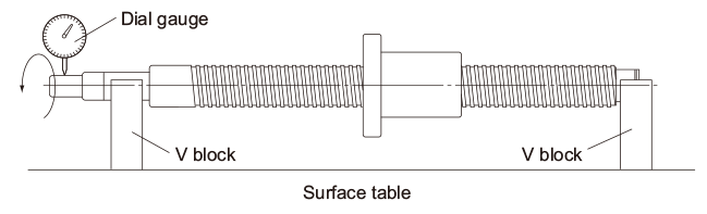
Radial Runout of the Grooved Surface of the Screw in Relation to the Bearing Journals (See Table 5)
Support the journals of the screw shaft on V blocks. Place a probe on the circumference of the nut, and record the largest difference measured by the dial gauge while rotating the screw shaft by one revolution without rotating the nut.
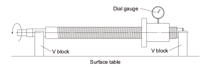
Axial Runout of the Journal End Face in Relation to the Bearing Journals (See Table 6)
Support the journals of the screw shaft on V blocks. Place a probe on the screw shaft’s journal end face, and record the largest difference measured by the dial gauge while rotating the screw shaft through one revolution.
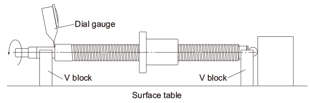
Axial Runout of the Flange Mounting Surface in Relation to the Screw Shaft Axis (See Table7)
Support the threaded portion of the screw shaft on V blocks near the nut. Place a probe on the flange end, and record the largest difference measured by the dial gauge while simultaneously rotating the screw shaft and the nut through one revolution.
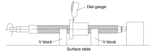
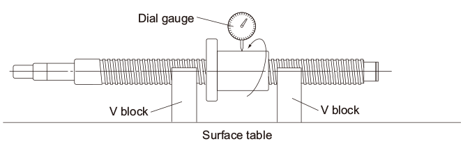
Radial Runout of the Nut Circumference in Relation to the Screw Shaft Axis (See Table 8 )
Support the threaded portion of the screw shaft on V blocks near the nut. Place a probe on the circumference of the nut, and record the largest difference measured by the dial gauge while rotating the nut through one revolution without rotating the screw shaft.
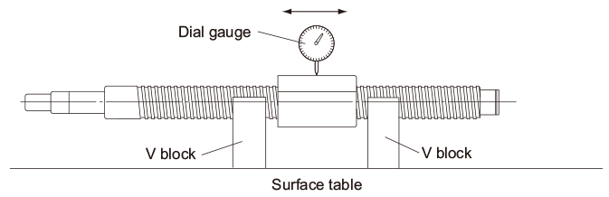
Parallelism of the Nut Circumference (Flat Mounting Surface) to the Screw Shaft Axis (See Table 9)
Support the threaded portion of the screw shaft on V blocks near the nut. Place a probe on the circumference of the nut (flat mounting surface), and record the largest difference measured by the dial gauge while moving the dial gauge in parallel with the screw shaft.
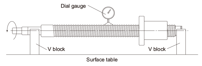
Overall Radial Runout of the Screw Diameter Relative to the Bearing Journals
Support the journals of the screw shaft on V blocks. Place a probe on the circumference of the screw shaft, and record the largest difference in the axial direction measured by the dial gauge at several points while rotating the screw shaft through one revolution.
- Note: For the permissible overall radial runout of the outer diameter of the screw in relation to the screw shaft axis at the journal, refer to JIS B 1192 (ISO 3408).
Axial Clearance
Axial Clearance of Precision Ball Screws
Table 10 shows the axial clearance of the precision ball screw. If the manufacturing length exceeds the value in Table 11, the resultant clearance may partially be negative (preload applied).
The manufacturing limit lengths of the ball screws compliant with the ISO standard are provided in Table 12. For the axial clearance of precision Caged Ball ball screws, see Precision Caged Ball Screw .
| Clearance symbol | G0 | GT | G1 | G2 | G3 |
|---|---|---|---|---|---|
| Axial clearance | 0 or less | 0 to 0.005 | 0 to 0.01 | 0 to 0.02 | 0 to 0.05 |
| Screw shaft outer diameter |
GT Clearance | G1 Clearance | G2 Clearance | |||||||||||
|---|---|---|---|---|---|---|---|---|---|---|---|---|---|---|
| C0 | C1 | C2・C3 | C5 | C0 | C1 | C2・C3 | C5 | C0 | C1 | C2 | C3 | C5 | C7 | |
| 4・6 | 80 | 80 | 80 | 100 | 80 | 80 | 80 | 100 | 80 | 80 | 80 | 80 | 100 | 120 |
| 8 | 230 | 250 | 250 | 200 | 230 | 250 | 250 | 250 | 230 | 250 | 250 | 250 | 300 | 300 |
| 10 | 250 | 250 | 250 | 200 | 250 | 250 | 250 | 250 | 250 | 250 | 250 | 250 | 300 | 300 |
| 12・13 | 440 | 500 | 500 | 400 | 440 | 500 | 500 | 500 | 440 | 500 | 630 | 680 | 600 | 500 |
| 14 | 500 | 500 | 500 | 400 | 500 | 500 | 500 | 500 | 530 | 620 | 700 | 700 | 600 | 500 |
| 15 | 500 | 500 | 500 | 400 | 500 | 500 | 500 | 500 | 570 | 670 | 700 | 700 | 600 | 500 |
| 16 | 500 | 500 | 500 | 400 | 500 | 500 | 500 | 500 | 620 | 700 | 700 | 700 | 600 | 500 |
| 18 | 720 | 800 | 800 | 700 | 720 | 800 | 800 | 700 | 720 | 840 | 1,000 | 1,000 | 1,000 | 1,000 |
| 20 | 800 | 800 | 800 | 700 | 800 | 800 | 800 | 700 | 820 | 950 | 1,000 | 1,000 | 1,000 | 1,000 |
| 25 | 800 | 800 | 800 | 700 | 800 | 800 | 800 | 700 | 1,000 | 1,000 | 1,000 | 1,000 | 1,000 | 1,000 |
| 28 | 900 | 900 | 900 | 800 | 1,100 | 1,100 | 1,100 | 900 | 1,300 | 1,400 | 1,400 | 1,400 | 1,200 | 1,200 |
| 30・32 | 900 | 900 | 900 | 800 | 1,100 | 1,100 | 1,100 | 900 | 1,400 | 1,400 | 1,400 | 1,400 | 1,200 | 1,200 |
| 36・40・45 | 1,000 | 1,000 | 1,000 | 800 | 1,300 | 1,300 | 1,300 | 1,000 | 2,000 | 2,000 | 2,000 | 2,000 | 1,500 | 1,500 |
| 50・55・63・70 | 1,200 | 1,200 | 1,200 | 1,000 | 1,600 | 1,600 | 1,600 | 1,300 | 2,000 | 2,500 | 2,500 | 2,500 | 2,000 | 2,000 |
| 80・100 | - | - | - | - | 1,800 | 1,800 | 1,800 | 1,500 | 2,000 | 4,000 | 4,000 | 4,000 | 3,000 | 3,000 |
| Shaft diameter |
GT clearance | G1 clearance | G2 clearance | ||||
|---|---|---|---|---|---|---|---|
| C3, Cp3 | C5, Cp5, Ct5 | C3, Cp3 | C5, Cp5, Ct5 | C3, Cp3 | C5, Cp5, Ct5 | C7, Cp7 | |
| 16 | 500 | 400 | 500 | 500 | 700 | 600 | 500 |
| 20, 25 | 800 | 700 | 800 | 700 | 1,000 | 1,000 | 1,000 |
| 32 | 900 | 800 | 1,100 | 900 | 1,400 | 1,200 | 1,200 |
| 40 | 1,000 | 800 | 1,300 | 1,000 | 2,000 | 1,500 | 1,500 |
| 50, 63 | 1,200 | 1,000 | 1,600 | 1,300 | 2,500 | 2,000 | 2,000 |
Axial Clearance of Rolled Ball Screw
Table 12 shows axial clearance of rolled ball screw.
| Screw shaft outer diameter | Axial clearance (maximum) |
|---|---|
| 6 to 12 | 0.05 |
| 14 to 28 | 0.1 |
| 30 to 32 | 0.14 |
| 36 to 45 | 0.17 |
| 50 | 0.2 |
Preload
A preload is applied in order to eliminate the axial clearance and minimize the displacement under an axial load.
A preload is generally used in applications requiring highly accurate positioning.
Rigidity of the Ball Screw under a Preload
When a preload is provided to a ball screw, the rigidity of the nut is increased.
Fig. 4 shows elastic displacement curves of a ball screw under a preload and without a preload.
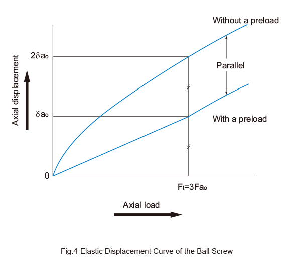
Fig. 5 shows a single-nut type of ball screw.
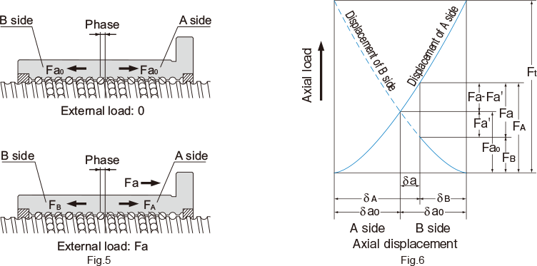
The A and B sides are provided with preload Fa0 by changing the groove pitch in the center of the nut to create a phase. Because of the preload, the A and B sides are elastically displaced by δa0 each. If an axial load (Fa) is applied from outside in this state, the displacement of the A and B sides is calculated as follows.

In other words, the loads on the A and B sides are expressed as follows:

Therefore, under a preload, the load that the A side receives equals Fa‒Fa'. This means that the displacement of the A side is smaller because load Fa', which is applied when the A side receives no preload, is deducted from Fa.
This effect extends to the point where the displacement (δa0) caused by the preload applied on the B side reaches zero.
To what extent is the elastic displacement reduced? The relationship between the axial load on the ball screw under no preload and the elastic displacement can be expressed by δa∝Fa2/3. From Fig. 6, the following equations are established.
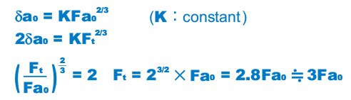
Thus, the ball screw under a preload is displaced by δa0 when an axial load (Ft) approximately three times greater than the preload is provided from outside. As a result, the displacement of the ball screw under a preload is half the displacement (2δa0 ) of the ball screw without a preload.
As stated above, since the preloading is effective up to approximately three times the applied preload, the optimum preload is one third of the maximum axial load.
Note that an excessive preload adversely affects the service life and heat generation. The maximum preload should be set at 10% of the basic dynamic load rating (Ca) in the axial direction.
Preload Torque
The preload torque of the ball screw is controlled in accordance with the JIS standard JIS B 1192 (ISO 3408).
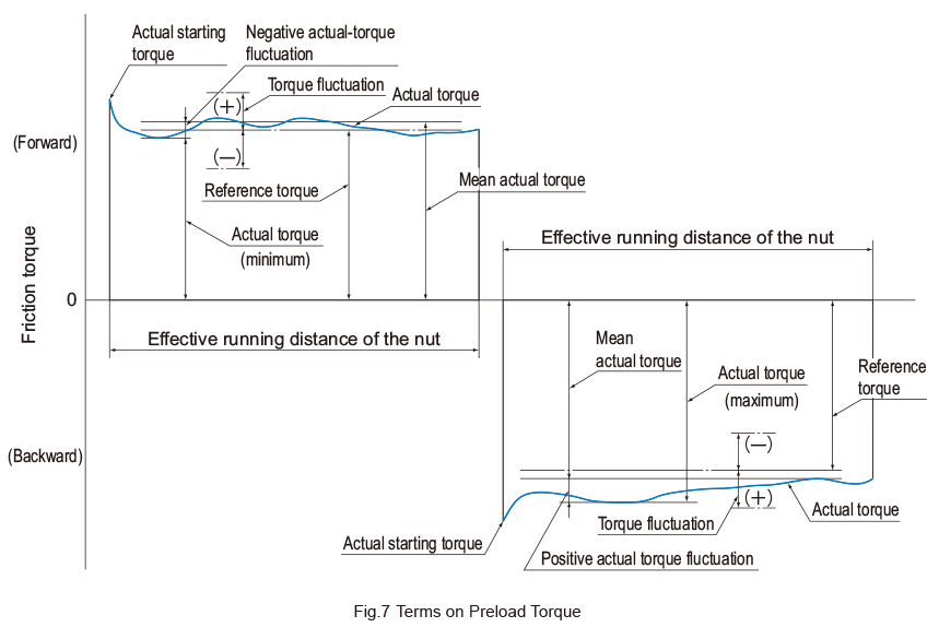
Dynamic Preload Torque
A torque required to continuously rotate the screw shaft of a ball screw under a given preload without an external load applied.
Actual Torque
A dynamic preload torque measured with an actual ball screw.
Torque Fluctuation
Variation in a dynamic preload torque set at a target value. It can be positive or negative in relation to the reference torque.
Coefficient of Torque Fluctuation
Ratio of torque fluctuation to the reference torque.
Reference Torque
A dynamic preload torque set as a target.
Calculating the Reference Torque
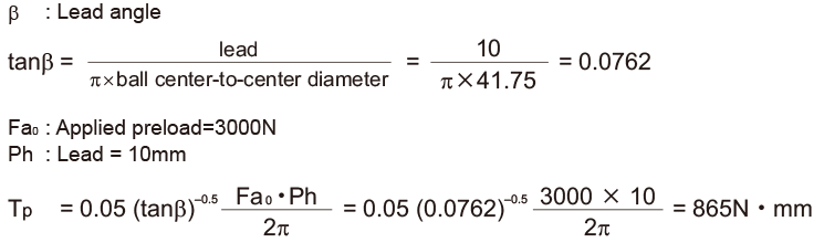
The reference torque of a ball screw provided with a preload is obtained in the following equation (4).
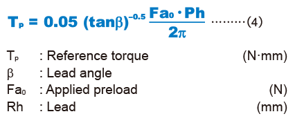
Note: The values listed above and the preload indicated on the delivery specification drawing are without retainers, grease, or seals.
Example: When a preload of 3,000 N is provided to the Mall Screw Model BIF4010-10G0 + 1500LC3 with a thread length of 1,300 mm (shaft diameter: 40 mm; ball center-to-center diameter: 41.75 mm; lead: 10 mm), the preload torque of the ball screw is calculated in the steps below.
Calculating the Reference Torque
Calculating the Torque Fluctuation

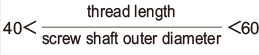
Thus, with the reference torque in Table 14 being between 600 and 1,000 N・mm, effective thread length 4,000 mm or less and accuracy grade C3, the coefficient of torque fluctuation is obtained as ±30%.
As a result, the torque fluctuation is calculated as follows.
865 × (1 ± 0.3) = 606 N・mm to 1,125 N・mm
Result
| Reference torque | 865 N・mn |
|---|---|
| Torque fluctuation | 606 N・mm to 1,125 N・mm |
| Reference torque N・mm |
Effective thread length | |||||||||||||
|---|---|---|---|---|---|---|---|---|---|---|---|---|---|---|
| 4,000mm or less | Above 4,000 mm and up to 10,000 mm |
|||||||||||||
 |
 |
- | ||||||||||||
| Accuracy grades | Accuracy grades | Accuracy grades | ||||||||||||
| Above | Up to | C0 | C1 | C3 | C5 | C7 | C0 | C1 | C3 | C5 | C7 | C3 | C5 | C7 |
| 200 | 400 | ±30% | ±35% | ±40% | ±50% | - | ±40% | ±40% | ±50% | ±60% | - | - | - | - |
| 400 | 600 | ±25% | ±30% | ±35% | ±40% | - | ±35% | ±35% | ±40% | ±45% | - | - | - | - |
| 600 | 1,000 | ±20% | ±25% | ±30% | ±35% | ±40% | ±30% | ±30% | ±35% | ±40% | ±45% | ±40% | ±45% | ±50% |
| 1,000 | 2,500 | ±15% | ±20% | ±25% | ±30% | ±35% | ±25% | ±25% | ±30% | ±35% | ±40% | ±35% | ±40% | ±45% |
| 2,500 | 6,300 | ±10% | ±15% | ±20% | ±25% | ±30% | ±20% | ±20% | ±25% | ±30% | ±35% | ±30% | ±35% | ±40% |
| 6,300 | 10,000 | - | - | ±15% | ±20% | ±30% | - | - | ±20% | ±25% | ±35% | ±25% | ±30% | ±35% |
Selection Criteria
- Operating Conditions of the Ball Screw
- Operating Conditions of the Ball Screw
- Selecting a Screw Shaft
- Selecting lead・Selecting a shaft diameter
- Mounting Procedure for the Ball Screw Shaft
- Permissible Axial Load
- Permissible Rotational Speed
- Selecting a Nut
- Calculating the Permissible Axial Load
- Considering the Service Life
- Considering the Rigidity
- Considering the Positioning Accuracy
- Considering the Rotational Torque
- Considering the Driving Motor
