Mounting Procedure for the Ball Screw Shaft
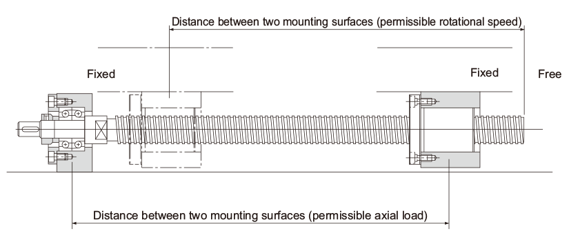
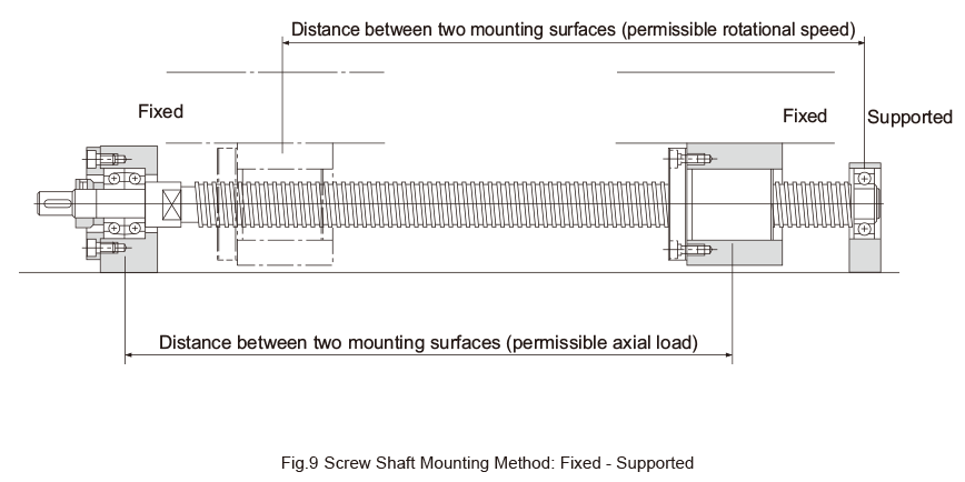
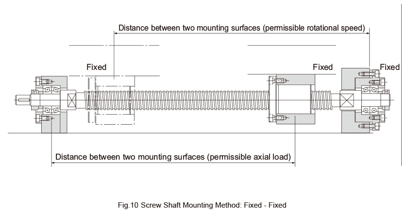
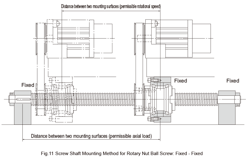
Fig. 8 to Fig. 11 show the representative mounting methods for the screw shaft.
The permissible axial load and the permissible rotational speed vary with mounting methods for the screw shaft. Therefore, it is necessary to select an appropriate mounting method according to the operating conditions.
Determining the Permissible Axial Load (Buckling Load on the Screw Shaft)
● For Fixed-Fixed Configuration (see Fig. 10, Fig. 11)
Calculate the buckling load for A and B (the distances between mounting surfaces) using formula 5 (see Permissible Axial Load), and use the smaller value as the screw shaft buckling load.
● For Fixed-Free, Fixed-Supported Configuration (see Fig. 8, Fig. 9)
Use B in formula 5 (see Permissible Axial Load) to calculate the screw shaft buckling load.
Determining the Permissible Screw Shaft Rotational Speed (Critical Speed of the Screw Shaft)
Calculate the critical speed for A and B (the distances between mounting surfaces) using formula 7 (see Permissible Rotational Speed), and use the smaller value as the screw shaft critical speed.
Selection Criteria
- Operating Conditions of the Ball Screw
- Operating Conditions of the Ball Screw
- Selecting a Screw Shaft
- Selecting lead・Selecting a shaft diameter
- Mounting Procedure for the Ball Screw Shaft
- Permissible Axial Load
- Permissible Rotational Speed
- Selecting a Nut
- Calculating the Permissible Axial Load
- Considering the Service Life
- Considering the Rigidity
- Considering the Positioning Accuracy
- Considering the Rotational Torque
- Considering the Driving Motor
