Considering the Positioning Accuracy
Causes of Error in the Positioning Accuracy
The causes of error in the positioning accuracy include the lead angle accuracy, the axial clearance, and the axial rigidity of the feed screw system. Other important factors include thermal displacement from heat and the orientation change of the guide system during traveling.
Considering the Lead Angle Accuracy
To satisfy required positioning accuracy, it is necessary to select the correct accuracy grade of the ball screw from the table of ball screw accuracies (see Table 1: Lead Angle Accuracy). Table 20 shows examples of selecting the accuracy grades by the application.
Considering the Axial Clearance
The axial clearance is not a factor of positioning accuracy in single-directional feed. However, it will cause a backlash when the feed direction or the axial load is inversed. Select an axial clearance that meets the required backlash from Table 10 and Table 12 in Axial Clearance.
| Applications | Shaft | Accuracy grades | ||||||||
|---|---|---|---|---|---|---|---|---|---|---|
| C0 | C1 | C2 | C3 | C5 | C7 | C8 | C10 | |||
| NC machine tools | Lathe | X | ● | ● | ● | ● | ||||
| Z | ● | ● | ||||||||
| Machining center | XY | ● | ● | ● | ||||||
| Z | ● | ● | ● | |||||||
| Drilling machine | XY | ● | ● | |||||||
| Z | ● | ● | ||||||||
| Jig borer | XY | ● | ● | |||||||
| Z | ● | ● | ||||||||
| Surface grinder | X | ● | ● | |||||||
| Y | ● | ● | ● | ● | ||||||
| Z | ● | ● | ● | ● | ||||||
| Cylindrical grinder | X | ● | ● | ● | ||||||
| Z | ● | ● | ● | |||||||
| Electric discharge machine |
XY | ● | ● | ● | ||||||
| Z | ● | ● | ● | ● | ||||||
| Electric discharge machine Wire cutting machine |
XY | ● | ● | ● | ||||||
| Z | ● | ● | ● | ● | ||||||
| UV | ● | ● | ● | |||||||
| Punching press | XY | ● | ● | ● | ||||||
| Laser beam machine | X | ● | ● | ● | ||||||
| Z | ● | ● | ● | |||||||
| Woodworking machine | ● | ● | ● | ● | ||||||
| General-purpose machine, dedicated machine | ● | ● | ● | ● | ● | |||||
| Industrial robots | Cartesian coordinate | Assembly | ● | ● | ● | ● | ||||
| Other | ● | ● | ● | ● | ||||||
| Vertical articulated type | Assembly | ● | ● | ● | ||||||
| Other | ● | ● | ||||||||
| Cylindrical coordinate | ● | ● | ● | |||||||
| Semiconductor manufacturing machines |
Photolithography machine | ● | ● | |||||||
| Chemical treatment machine | ● | ● | ● | ● | ● | ● | ||||
| Wire bonding machine | ● | ● | ||||||||
| Prober | ● | ● | ● | ● | ||||||
| Printed circuit board drilling machine | ● | ● | ● | ● | ● | |||||
| Electronic component inserter | ● | ● | ● | ● | ||||||
| 3D measuring instrument | ● | ● | ● | |||||||
| Image processing machine | ● | ● | ● | |||||||
| Injection molding machine | ● | ● | ● | |||||||
| Office equipment | ● | ● | ● | ● | ||||||
Considering the Axial Rigidity in the Feed Screw System
Of the axial rigidities of the feed screw system, the axial rigidity of the screw shaft fluctuates according to the stroke position. When the axial rigidity is large, such change in the axial rigidity of the screw shaft will affect the positioning accuracy. Therefore, it is necessary to take into account the rigidity of the feed screw system (Considering the Rigidity).
Example: Positioning error due to the axial rigidity of the feed screw system during a vertical transfer
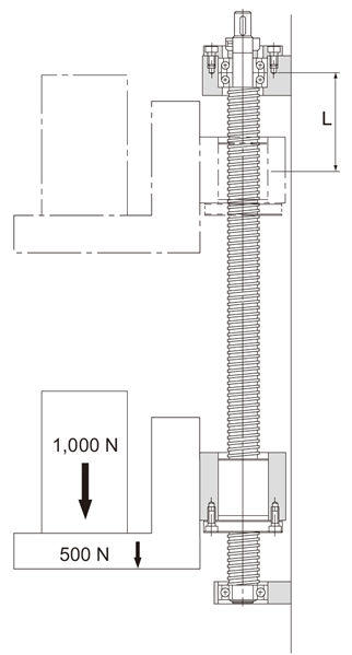
Operating Conditions
Transferred weight: 1,000 N; table weight: 500 N
Ball screw used: model BNF2512-2.5 (screw-shaft thread minor diameter d1 = 21.9 mm)
Stroke length: 600 mm (L = 100 mm to 700 mm)
Screw shaft mounting type: fixed-supported
Consideration
The difference in axial rigidity between L = 100 mm and L = 700 mm applied only to the axial rigidity of the screw shaft.
Therefore, positioning error due to the axial rigidity of the feed screw system equals the difference in the axial displacement of the screw shaft between L = 100 mm and L = 700 mm.
Axial Rigidity of the Screw Shaft (see Axial rigidity of the screw shaft)
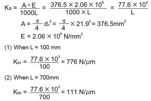
Axial Displacement due to Axial Rigidity of the Screw Shaft
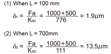
Positioning Error due to Axial Rigidity of the Feed Screw System

Therefore, the positioning error due to the axial rigidity of the feed screw system is 11.6 μm.
Considering the Thermal Displacement through Heat Generation
If the temperature of the screw shaft increases during operation, the screw shaft will elongate due to heat, thereby lowering the positioning accuracy. The expansion and contraction of the screw shaft is calculated using equation (43) below.

| Δℓ | Axial expansion/contraction of the screw shaft (mm) |
|---|---|
| ρ | Thermal expansion coefficient (12 × 10-6 / °C) |
| Δt | Temperature change in the screw shaft (°C) |
| ℓ | Effective thread length (mm) |
Thus, if the temperature of the screw shaft increases by 1°C, the screw shaft is elongated by 12 μm per meter. Therefore, as the ball screw travels faster, more heat is generated, and as the temperature increases, the positioning accuracy lowers. Accordingly, if high accuracy is required, it is necessary to take measures to cope with the temperature increase.
Measures to Cope with the Temperature Increase
Minimize the Heat Generation
- Minimize the preloads on the ball screw and the support bearing.
- Increase the ball screw lead and reduce the rotational speed.
- Select a correct lubricant. (See Lubrication Accessories.)
- Cool the circumference of the screw shaft with a lubricant or air.
Avoid the Effects of Increasing Temperature through Heat Generation
- Set a negative target value for the reference travel distance of the ball screw.
Generally, set a negative target value for the reference travel distance assuming a temperature increase of 2°C to 5°C by heat (-0.02 mm to -0.06 mm/m). - Preload the shaft screw with tension. (See Fig. 10 of the structure on Mounting Procedure for the Ball Screw Shaft.)
Considering the Orientation Change during Travel
The lead angle accuracy of the ball screw equals the positioning accuracy of the center of the shaft of the ball screw. Normally, the point where the highest positioning accuracy is required changes according to the ball screw center and the vertical or horizontal direction. Therefore, the orientation change during travel affects the positioning accuracy.
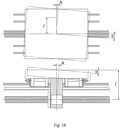
The largest factor of orientation change affecting the positioning accuracy is pitching if the change occurs in the ball screw center and the vertical direction, and yawing if the change occurs in the horizontal direction.
Accordingly, it is necessary to study the orientation change (accuracy in pitching, yawing, etc.) during the traveling on the basis of the distance from the ball screw center to the location where positioning accuracy is required.
Positioning error due to pitching and yawing is obtained using equation (44) below.

Selection Criteria
- Operating Conditions of the Ball Screw
- Operating Conditions of the Ball Screw
- Selecting a Screw Shaft
- Selecting lead・Selecting a shaft diameter
- Mounting Procedure for the Ball Screw Shaft
- Permissible Axial Load
- Permissible Rotational Speed
- Selecting a Nut
- Calculating the Permissible Axial Load
- Considering the Service Life
- Considering the Rigidity
- Considering the Positioning Accuracy
- Considering the Rotational Torque
- Considering the Driving Motor
