Calculating the permissible axial load
In Horizontal Mount
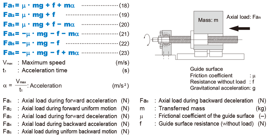
With ordinary conveyance systems, the axial load (Fan) applied when horizontally reciprocating the work is obtained in the equation below.
In Vertical Mount
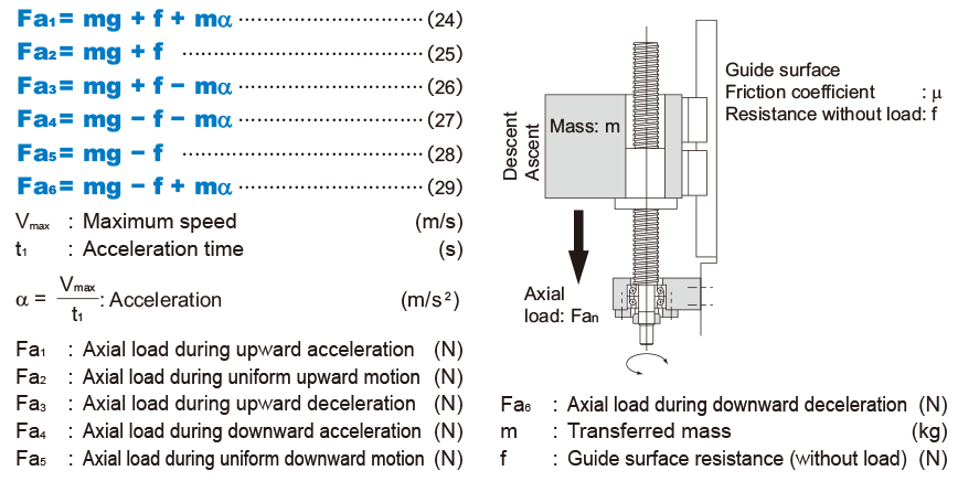
With ordinary conveyance systems, the axial load (Fan) applied when vertically reciprocating the work is obtained in the equation below.
Static Safety Factor
Static Safety Factor per Basic Static Load Rating (Excluding Models HBN-V, HBN-K (KA), HBN, and SBKH)
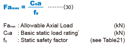
For ball screws, a static safety factor as defi ned by formula 30 based on the calculated maximum axial load and static load rating must be considered. Vibrations, impacts, or inertia due to starting and stopping may result in an unexpectedly large load. Therefore, please confi rm that a suffi cient static safety factor has been ensured when selecting a model. Table 21 shows guideline values for the static safety factor.
| Load conditions | Lower limit of fs |
|---|---|
| Without vibration or impact | 2 |
| With vibration or impact | 5 |
Permissible Load Safety Margin (Models HBN-V, HBN-K (KA), HBN, and SBKH)
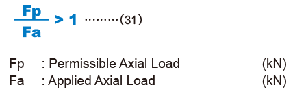
The permissible load Fp in the axial direction is fi xed for high-load ball screw models HBN-V, HBN-K (KA), HBN, and SBKH. Therefore, please select a model with a calculated maximum axial load (Famax ) that does not exceed the permissible load (Fp). Permissible load (Fp) indicates the maximum axial load that the high-load ball screw can receive, and this range should not be exceeded.
1 The basic static load rating (C0a) is a static load with a constant direction and magnitude whereby the sum of the permanent deformation of the rolling element and that of the raceway on the contact area under the maximum stress is 0.0001 times the rolling element diameter. With the ball screw, it is defi ned as the axial load. (Specifi c values for each ball screw model are indicated in the dimensional tables for the corresponding model.)
2 The maximum load in the axial direction calculated on Calculating the Axial Load is applied to the maximum axial load (Fa max ).
3 Vibrations and impacts are typically caused by factors such as acceleration and deceleration, sudden starting and stopping, vibrations and impacts from an external machine, and changes in processing power over time.
Selection Criteria
- Conditions of the Ball Screw
- Conditions of the Ball Screw
- Estimating the shaft length
- Selecting lead・Selecting a shaft diameter
- Method for Mounting the Ball Screw Shaft
- Permissible Axial Load
- Permissible Rotational Speed
- Selecting a Nut
- Calculating the permissible axial load
- Studying the Service Life
- Studying the Rigidity
- Studying the Positioning Accuracy
- Studying the Rotational Torque
- Studying the Driving Motor